
An anti-deviation mechanism that can be used in combination with textile winding machines of different specifications

A winding machine and anti-deflection technology, which is applied in the direction of coiling strips, thin material handling, transportation and packaging, etc. It can solve the problems of adjusting the limit plate, inconvenient adjustment of the height of the limit roller and limit plate, and inconvenience

Active Publication Date: 2021-03-09
吴江桑尚丝绸有限公司
View PDF5 Cites 0 Cited by
  • Summary
  • Abstract
  • Description
  • Claims
  • Application Information

AI Technical Summary

Problems solved by technology

[0007] The object of the present invention is to provide an anti-deviation mechanism that can be used in combination with textile winding machines of different specifications, so as to solve the problem that the existing anti-deflection mechanism for textile winding machines proposed in the above background technology is inconvenient to adjust the limit. The height of the positioning roller and the limiting plate, and it is not convenient to adjust the distance between the limiting plates and the distance between the limiting rollers according to the width and thickness of the fabric

Method used


Image

  • An anti-deviation mechanism that can be used in combination with textile winding machines of different specifications
  • An anti-deviation mechanism that can be used in combination with textile winding machines of different specifications
  • An anti-deviation mechanism that can be used in combination with textile winding machines of different specifications

Examples


Embodiment Construction

[0033] The following will clearly and completely describe the technical solutions in the embodiments of the present invention with reference to the accompanying drawings in the embodiments of the present invention. Obviously, the described embodiments are only some, not all, embodiments of the present invention. Based on the embodiments of the present invention, all other embodiments obtained by persons of ordinary skill in the art without making creative efforts belong to the protection scope of the present invention.

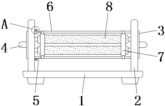
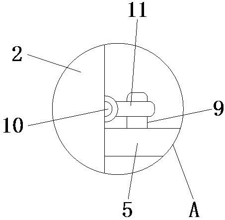
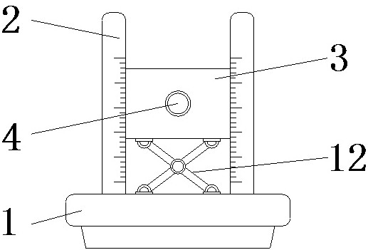
[0034] see Figure 1-10, the present invention provides a technical solution: an anti-deviation mechanism that can be used in combination with textile winding machines of different specifications, including a support plate 1, a clamping rod 2, a mounting block 3, a driving rod 4, a prism part 401, a cylindrical part 402, reset shaft 5, bushing 6, limit plate 7, limit roller 8, lever 9, reset shaft 10, limit block 11, support frame 12, chute 13, slider 14, worm...


PUM


Abstract

The invention discloses an anti-deflection mechanism enabling combined use with spinning winding machines of different specification sizes. The anti-deflection mechanism comprises a supporting plate,wherein clamping rods are disposed on the upper end of the supporting plate; an installation block is clamped between the clamping rods in a slide manner; a slide groove is formed in the upper surfaceof the supporting plate and disposed between the clamping rods; a slide block is clamped in the slide groove in a slide manner; the upper end of the slide block is in shaft connection to the lower end of the supporting frame; the upper end of the supporting frame is in shaft connection to a threaded sleeve; the threaded sleeve is in threaded connection to the outer side of a threaded rod; the twoends of the threaded rod are in bearing connection to the lower part of the inner end of the installation block; a worm wheel is in key connection to the middle of the threaded rod; the worm wheel isconnected to a driving rod through a worm rod sleeve; and the driving rod passes through the worm rod sleeve. The anti-deflection mechanism enabling combined use with the spinning winding machines ofthe different specification sizes has the beneficial effects that the heights of limiting plates and the heights of limiting rollers can be adjusted easily, and distances between the limiting rollersand distances between the limiting plates can be adjusted easily, so the anti-deflection mechanism can be adapted to the spinning winding machines with the different sizes.

Description

technical field [0001] The invention relates to the technical field related to textiles, in particular to an anti-deviation mechanism that can be used in combination with textile winding machines of different specifications. Background technique [0002] The textile winding machine is a device for winding cloth. It is often used with the anti-deflection mechanism during use. This is because the cloth is easy to deviate during the winding process of the textile winding machine, and may be Wrinkles occur, so that when the cloth is wound on the cloth roll, the phenomenon of wrinkling occurs, which is not convenient for the storage of the cloth. The anti-deflection mechanism is a device that can prevent the cloth from being wrinkled on the cloth roll. [0003] However, the existing anti-deflection mechanism for textile winding machines also has the following problems in use: [0004] 1) When the existing anti-deflection mechanism for textile winders is in use, it is not conveni...

Claims


Application Information

Patent Timeline
Patent Type & Authority Patents(China)
IPC IPC(8): B65H23/038
CPCB65H23/038
Inventor 陈九娟
Owner 吴江桑尚丝绸有限公司
Learn More