Shock absorber bearing load simulation test device

A shock absorber bearing and load simulation technology, which is applied in the direction of mechanical bearing testing, etc., can solve the problems affecting the flatness measurement of shock absorber bearings and the inaccuracy of detection.

Active Publication Date: 2020-01-24
C&U CO LTD +1
View PDF6 Cites 1 Cited by
  • Summary
  • Abstract
  • Description
  • Claims
  • Application Information

AI Technical Summary

Problems solved by technology

[0002] shock absorber bearings such as figure 1 The shown generally includes an inner ring 6 and an outer ring 5, rollers are arranged between the inner ring 6 and the outer ring 5, a step 51 is arranged on the inner peripheral wall of the outer ring 5, the end face of the outer ring 5 is inclined, and there are also on the outer peripheral wall of the outer ring 51 There is a notch 52 usually provided for auxiliary positioning during installation. During actual use, a certain amount of load will be applied to the inclined surface of the shock absorber bearing. In order to simulate the actual working conditions, the production testing process It is necessary to simulate the load force of the shock absorber bearing. The current detection mostly adopts the method of pressing a heavy object on the outer ring of the shock absorber bearing to simulate the load situation of the actual working condition. However, in this way, the load on the inclined plane Heavy objects often cover the slope of the shock absorber bearing, which affects the subsequent measurement of the flatness and position of the shock absorber bearing, and the existing detection method is not accurate enough

Method used


Image

  • Shock absorber bearing load simulation test device
  • Shock absorber bearing load simulation test device
  • Shock absorber bearing load simulation test device

Examples


Embodiment Construction

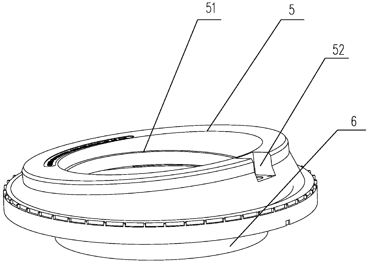
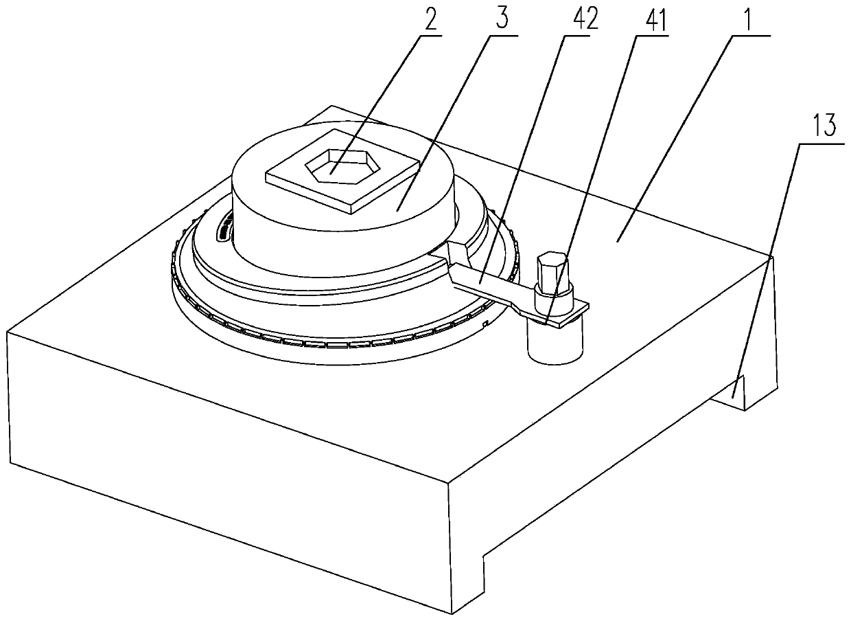
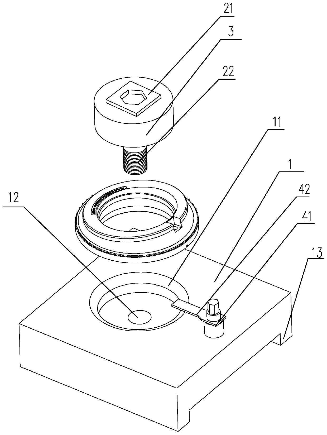
[0015] Depend on figure 2 with image 3 Disclosed is a shock absorber bearing load simulation test device, comprising a base 1, the base 1 is provided with a mounting groove 11 for mounting a bearing to be tested, the bottom surface of the mounting groove 11 is provided with a positioning hole 12, and the positioning hole 12 The upper thread is matched with a positioning screw 2, and the positioning screw 2 is provided with a positioning plate 3 along the circumference. The end is connected with a torque meter, and the base 1 is provided with a positioning piece on the side of the installation groove 11 for limiting the rotation of the bearing to be tested. The beneficial effect of this setting is: adopt the above scheme, set the steps passing through the inner side of the outer ring of the bearing in this way, use the structural characteristics of the bearing to be tested, and use the torque calculation to convert the load on the slope in actual use to that of the shock abs...


PUM


Abstract

The invention discloses a shock absorber bearing load simulation test device. The shock absorber bearing load simulation test device comprises a base, wherein a mounting groove for mounting a to-be-tested bearing is formed in the base; a positioning hole is formed in the bottom surface of the mounting groove; a positioning screw is in threaded fit with the positioning hole; a positioning disc is arranged on the positioning screw in the circumferential direction; the positioning disc is propped against a step on the inner wall of the outer ring of the to-be-tested bearing to position the to-be-tested bearing; the end part of the positioning screw is connected with a torque meter; and a positioning piece for limiting the rotation of the to-be-tested bearing is further arranged on one side ofthe mounting groove on the base. The shock absorber bearing load simulation test device can effectively perform a simulation test on the shock absorber bearing load, and meanwhile, does not affect the measurement of the flatness and the position degree of an inclined surface.

Description

technical field [0001] The invention relates to the technical field of bearing detection, in particular to a shock absorber bearing load simulation test device. Background technique [0002] shock absorber bearings such as figure 1 The shown generally includes an inner ring 6 and an outer ring 5, rollers are arranged between the inner ring 6 and the outer ring 5, a step 51 is arranged on the inner peripheral wall of the outer ring 5, the end face of the outer ring 5 is inclined, and there are also on the outer peripheral wall of the outer ring 51 There is a notch 52 usually provided for auxiliary positioning during installation. During actual use, a certain amount of load will be applied to the inclined surface of the shock absorber bearing. In order to simulate the actual working conditions, the production testing process It is necessary to simulate the load force of the shock absorber bearing. The current detection mostly adopts the method of pressing a heavy object on th...

Claims


Application Information

Patent Timeline
Patent Type & Authority Applications(China)
IPC IPC(8): G01M13/04
CPCG01M13/04
Inventor 郭新恒
Owner C&U CO LTD
Why Eureka
Try Eureka