
A radar signal phase difference detection method for fixed targets

A phase difference detection and radar signal technology, applied in the field of signal processing, can solve the problems of complex environment, difficult to satisfy anti-jamming and detection accuracy at the same time, and difficult to satisfy noise immunity and detection accuracy at the same time.

Active Publication Date: 2020-07-10
长沙科瑞德电气有限公司
View PDF4 Cites 0 Cited by
  • Summary
  • Abstract
  • Description
  • Claims
  • Application Information

AI Technical Summary

Problems solved by technology

[0003] In practical applications, due to the complex environment of the measured fixed target, there may be a large amount of suspended particulate matter, unevenness of the measurement channel and other factors, resulting in low accuracy of the position measurement results of the fixed target
The current radar signal phase difference detection method for fixed targets is difficult to meet the requirements of anti-jamming and detection accuracy in practical applications. Therefore, it is necessary to explore new high-precision detection methods for radar signal phase difference and conduct in-depth research on the position measurement technology of fixed targets. , comprehensive research to meet practical application requirements
[0004] The method proposed by the invention overcomes the shortcomings that the traditional radar signal phase difference detection method is difficult to meet the requirements of noise resistance and detection accuracy at the same time

Method used


Image

  • A radar signal phase difference detection method for fixed targets
  • A radar signal phase difference detection method for fixed targets
  • A radar signal phase difference detection method for fixed targets

Examples


Embodiment 1

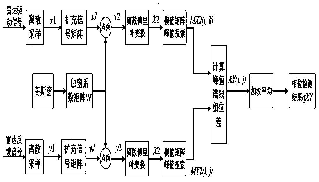
[0028] A radar signal phase difference detection method for a fixed target, the steps are as follows:

[0029] Step 1: The radar driving signal x transmitted by the transmitting antenna and the radar feedback signal y received by the receiving antenna are sent to the analog-to-digital converter, and the radar driving signal x1 and the radar feedback signal y1 of length N after discrete sampling are respectively obtained, where The sampling frequency is fs, and N is an integer power of 2. According to the sampling theorem, the frequency fs should be greater than twice the highest frequency of the radar driving signal;

[0030] Step 2: Use the Gaussian window function to construct a windowing coefficient matrix W, the number of columns of the windowing coefficient matrix W is N, and the number of rows is log2(N), wherein the i-th row of the windowing coefficient matrix W has a length of N, coefficient is σ(i), the i-th row of Gaussian window coefficient σ(i)=i / log2(N), and the e...

Embodiment 2

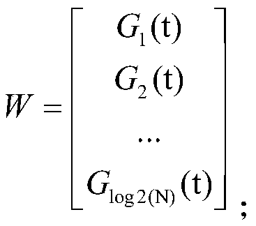
[0041] On the basis of embodiment 1, the expression of the Gaussian window Gi (t) in the windowing coefficient matrix in the described step 2 is:

[0042] , where t is a time variable, t=0,1,2,3,...,N-1;

Embodiment 3

[0044] On the basis of embodiment 1, the windowing processing method in the said step 3 is to expand the discrete sampling sequence x1 and y1 with a length of N into a matrix with a column number of N and a row number of log2(N), wherein Each row in the matrix is ​​x1 and y1 respectively, and the expanded matrix expressions are:

[0045] and ,

[0046] Then xJ and yJ are respectively dot-multiplied with the windowing coefficient matrix W to obtain the signal matrix x2 and y2 after windowing.


PUM


Abstract

The invention relates to a radar signal phase difference detection method aiming at a fixed target. A radar signal is subjected to weighting processing by using Gaussian windows with different widths;the frequency spectrum interference of an interference signal on a useful frequency ingredient is reduced from different time-frequency scale; through weighting averaging of discrete frequency spectrum peak phase differences, a high-precision calculation result of a radar signal phase difference is obtained; and the defect that a conventional radar signal phase difference detection method is difficult to simultaneously meet the requirements of noise resistance and detection precision is overcome.

Description

technical field [0001] The invention belongs to the technical field of signal processing, and in particular relates to a radar signal phase difference detection method for a fixed target. Background technique [0002] With the microwave as the carrier, the position of the fixed target is measured according to the phase difference between the transmitted signal and the transmitted signal, which has the advantages of not being affected by weather conditions and flexible measurement point arrangement. [0003] In practical applications, due to the complex environment of the measured fixed target, there may be a large amount of suspended particulate matter, the unevenness of the measurement channel and other factors, resulting in low accuracy of the position measurement results of the fixed target. The current radar signal phase difference detection method for fixed targets is difficult to meet the requirements of anti-jamming and detection accuracy in practical applications. Th...

Claims


Application Information

Patent Timeline
Patent Type & Authority Patents(China)
IPC IPC(8): G01S7/41
CPCG01S7/41
Inventor 刘一江温和祝高锋
Owner 长沙科瑞德电气有限公司
Learn More