Supercharge Your Innovation With Domain-Expert AI Agents!

Optical fiber OTDR dead zone eliminator and dead zone eliminating method thereof

An eliminator, optical fiber technology, applied in electromagnetic wave transmission systems, electrical components, transmission systems, etc., to achieve accurate insertion loss, improve accuracy, and reduce test time.

Pending Publication Date: 2020-01-24
江苏中吉电科网络技术有限公司
View PDF0 Cites 0 Cited by
  • Summary
  • Abstract
  • Description
  • Claims
  • Application Information

AI Technical Summary

Problems solved by technology

OTDR will produce blind spots because the detector of OTDR is temporarily "blind" under the influence of high-intensity Fresnel reflected light

Method used


Image

  • Optical fiber OTDR dead zone eliminator and dead zone eliminating method thereof
  • Optical fiber OTDR dead zone eliminator and dead zone eliminating method thereof
  • Optical fiber OTDR dead zone eliminator and dead zone eliminating method thereof

Examples


Embodiment 1

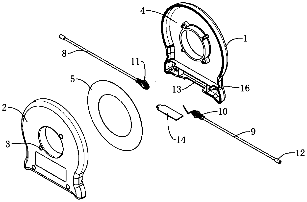
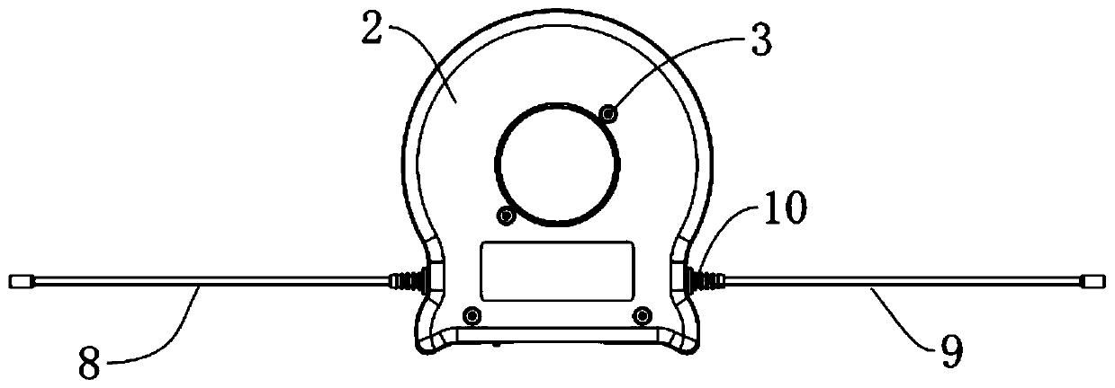
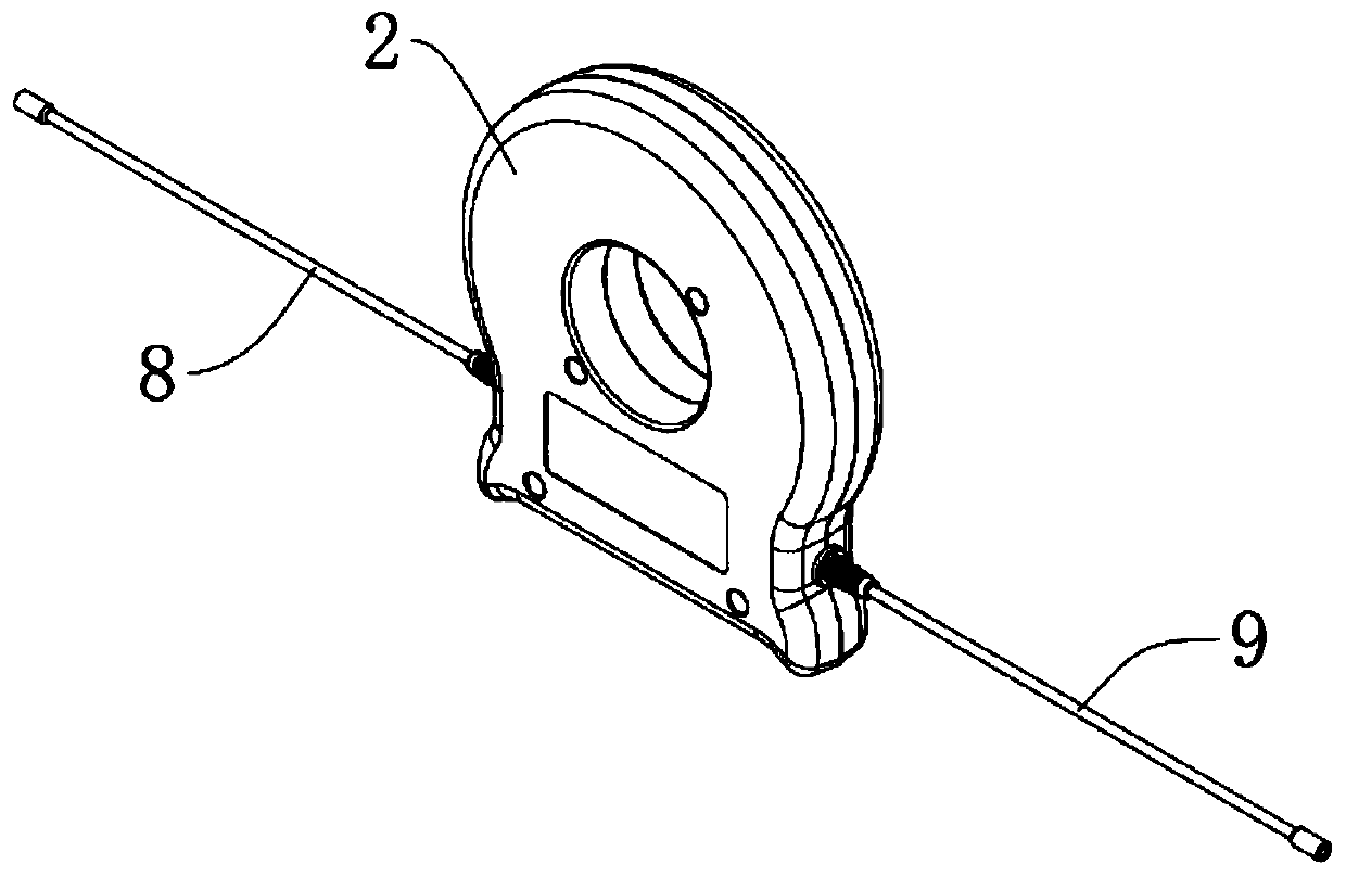
[0021] Please refer to the attached figure 1 , 2 , 3 and 5, a kind of optical fiber OTDR dead zone eliminator, comprises circular shell a1 and circular shell b2, mutual clamping between described circular shell a1 and circular shell b2, and circular shell a1 and circular shell The b2 is connected and fixed by the fixing bolt 3, and the circular shell a1 and the circular shell b2 are set to fix the optical fiber disk 5 in the circular shell a1 and the circular shell b2, and the circular shell a1 and the circular shell b2 A storage space box 13 is provided below the storage space box 13, and a box cover 14 is covered under the storage space box 13, and an optical fiber disc slot 4 is arranged inside the circular shell a1 and the circular shell b2, and the optical fiber disc An optical fiber disk 5 is clamped in the card slot 4, and an optical fiber 6 is wound on the optical fiber disk 5. The optical fiber 6 provided is a guiding optical fiber, and the length of the optical fibe...

Embodiment 2

[0030] Please refer to the attached figure 1 , 2 , 3 and 4, a kind of optical fiber OTDR dead zone eliminator, comprises circular shell a1 and circular shell b2, mutual clamping between described circular shell a1 and circular shell b2, and circular shell a1 and circular shell The b2 is connected and fixed by the fixing bolt 3, and the circular shell a1 and the circular shell b2 are set to fix the optical fiber disk 5 in the circular shell a1 and the circular shell b2, and the circular shell a1 and the circular shell b2 A storage space box 13 is provided below the storage space box 13, and a box cover 14 is covered under the storage space box 13, and an optical fiber disc slot 4 is arranged inside the circular shell a1 and the circular shell b2, and the optical fiber disc An optical fiber disk 5 is clamped in the card slot 4, and an optical fiber 6 is wound on the optical fiber disk 5. The optical fiber 6 provided is a guiding optical fiber, and the length of the optical fibe...


PUM


Abstract

The invention discloses an optical fiber OTDR dead zone eliminator. The device comprises a circular shell a and a circular shell b, the circular shell a and the circular shell b are clamped with eachother; the circular shell a and the circular shell b are connected and fixed through a fixing bolt; a storage space box is arranged below the circular shell a and the circular shell b; a box cover covers the lower part of the storage space box; optical fiber disc clamping grooves are formed in the circular shell a and the circular shell b; an optical fiber disc is clamped in the optical fiber discclamping groove; an optical fiber is wound on the optical fiber disc; the two ends of the optical fiber are connected with a leading-out optical fiber a and a leading-out optical fiber b through optical fiber connectors. A limiting disc is arranged on one side of the clamping groove, a guide optical fiber pair is adopted, a blind area generated during optical fiber testing is eliminated, the testing accuracy is greatly improved, and a user can rapidly and accurately measure the insertion loss in a link and roughly know the condition of the detected optical fiber link through the guide opticalfiber pair.

Description

technical field [0001] The invention belongs to the technical field of optical fiber communication, and in particular relates to an optical fiber OTDR blind zone eliminator and a blind zone eliminating method thereof. Background technique [0002] For technical workers and fiber optic installation workers in the fiber optic communication industry, Optical Time Domain Reflectometer (OTDR, Optical Time Domain Reflectometer) is a common fiber testing tool. In order to maximize the performance of OTDR, it is necessary to Various factors have a certain degree of understanding. Among the many influencing factors, the blind zone is one of the important influencing factors. When the OTDR detects the optical fiber link, due to the influence of reflection, it cannot detect or accurately locate the optical fiber link within a certain distance. event and failure points. The distance here is what we call the dead zone. OTDR will produce blind spots because the detector of OTDR is tempo...

Claims


Application Information

Patent Timeline
IPC IPC(8): H04B10/071
CPCH04B10/071
Inventor 喻贵健
Owner 江苏中吉电科网络技术有限公司
Features
  • R&D
  • Intellectual Property
  • Life Sciences
  • Materials
  • Tech Scout
  • Unparalleled Data Quality
  • Higher Quality Content
  • 60% Fewer Hallucinations
Learn More