Precise positioning type grabbing equipment of crane and working method thereof

A precise positioning and crane technology, applied in the direction of load hanging components, transportation and packaging, etc., can solve the problems of safety, inability to accurately locate the grasping position of the equipment, hidden dangers, etc., and achieve the effect of firm grasping

Inactive Publication Date: 2020-02-04
合肥市春华起重机械有限公司
View PDF7 Cites 0 Cited by
  • Summary
  • Abstract
  • Description
  • Claims
  • Application Information

AI Technical Summary

Problems solved by technology

[0005] The purpose of the present invention is to solve the problem in the prior art that the operator constantly adjusts and controls the position of the grippers when the crane is grabbing, so that the grippers can be more convenient and more evenly distributed on the grippers, so that The equipment and items of the gripper are more stable and stable, but the manual operation results in more human and material resources for the grabbing work, and it is also impossible to accurately locate the grabbing position of the equipment that needs to be grabbed; when the gripper is in progress In the process of grasping, there will be misgrasping, grasping is not firm or loose during the process of grasping and moving, so there will be safety hazards, and it will also cause certain damage to the equipment that needs to be grasped, affecting the need to grasp. Due to the problem of normal use of the equipment, a crane precise positioning grabbing equipment and its working method are proposed

Method used


Image

  • Precise positioning type grabbing equipment of crane and working method thereof
  • Precise positioning type grabbing equipment of crane and working method thereof
  • Precise positioning type grabbing equipment of crane and working method thereof

Examples


Embodiment Construction

[0032]The technical solutions of the present invention will be clearly and completely described below in conjunction with the embodiments. Apparently, the described embodiments are only some of the embodiments of the present invention, not all of them. Based on the embodiments of the present invention, all other embodiments obtained by persons of ordinary skill in the art without creative efforts fall within the protection scope of the present invention.

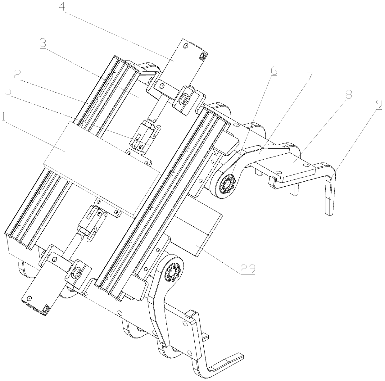
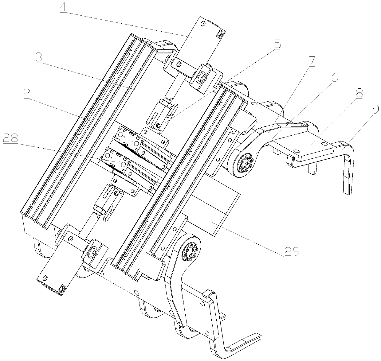
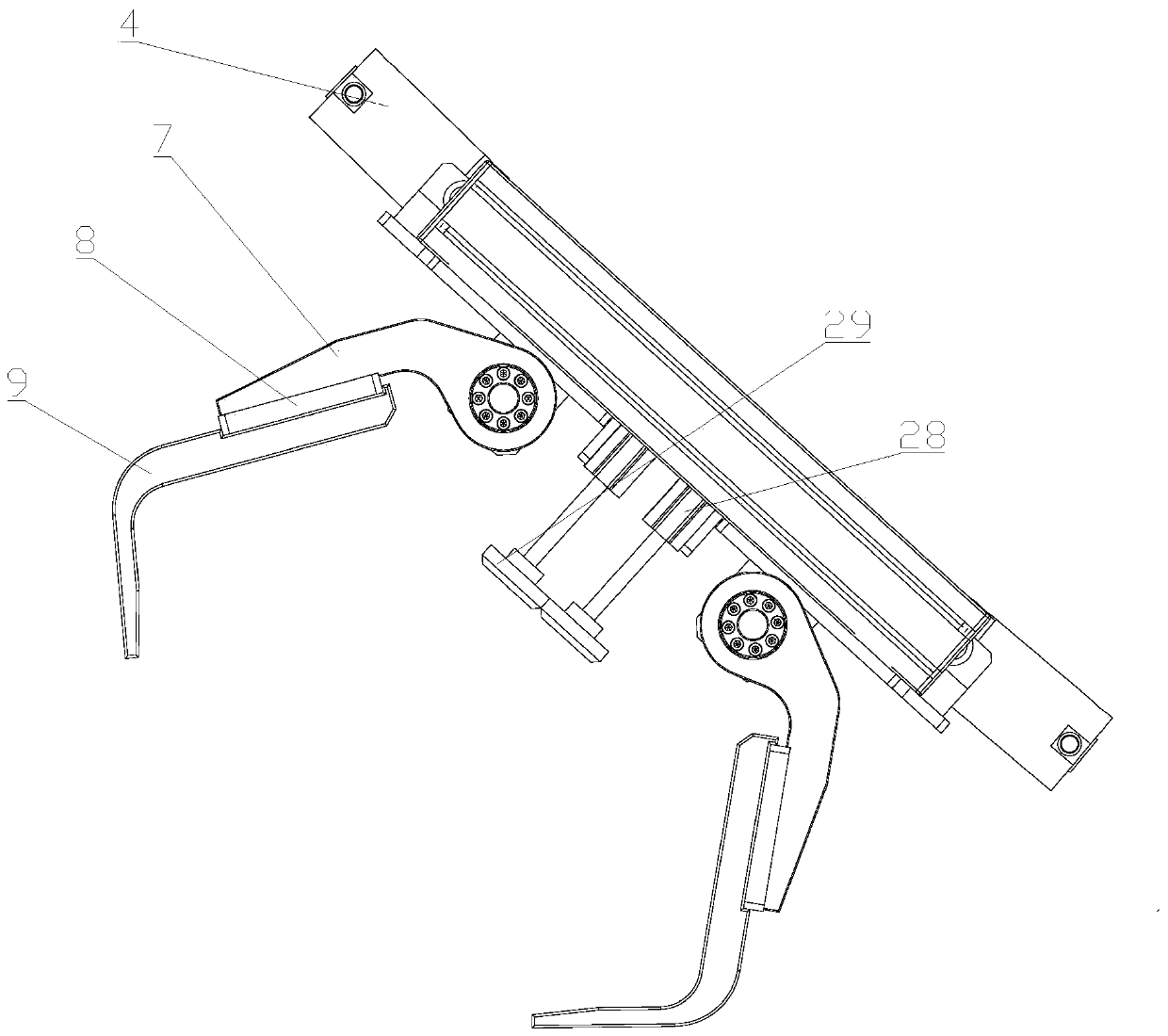
[0033] Such as Figure 1-7 As shown in the figure, a grabbing device for accurate positioning of a crane includes a mounting base 1 and a grabbing mechanism. The two sides of the bottom surface of the mounting base 1 are respectively provided with a long fixed plate 2, and the two sides of the bottom surface of the fixed plate 2 of the two groups are respectively provided has a grabbing mechanism;

[0034] The grabbing mechanism includes a mounting plate 3, a first hydraulic cylinder 4, a connecting plate 5, a connecting sh...


PUM


Abstract

The invention discloses precise positioning type grabbing equipment of a crane. The precise positioning type grabbing equipment of the crane comprises a mounting seat and grabbing mechanisms, the twosides of the bottom surface of the mounting seat are provided with strip-shaped fixing plates correspondingly, the two sides of the bottom surfaces of the two fixing plates are provided with the grabbing mechanisms correspondingly, a mounting plate is arranged on the bottom surfaces of the fixing plates, a first hydraulic cylinder is movably arranged on the side, away from the mounting seat, of the top surface of the mounting plate, the output end of the first hydraulic cylinder is movably connected with a connecting plate, the mounting plate is provided with a through hole matched with the connecting plate, the middle of the connecting plate sleeves a connecting shaft, the two sides of the connecting shaft are arranged on the bottom surface of the mounting plate through bearing seats correspondingly, shells are arranged on the two sides of the side wall of one fixing plate correspondingly, locking mechanisms are arranged in the shells, swing arms sleeve the two sides of the connectingshaft correspondingly, the other ends of the swing arms are connected with connecting seats, and the connecting seats are connected with gripper bodies through distance varying mechanisms. The precise positioning type grabbing equipment of the crane has the advantages that precise positioning can be performed for grabbing, and safety and stability are high during grabbing.

Description

technical field [0001] The invention belongs to the technical field of cranes, and relates to a grabbing device and a working method thereof, in particular to a crane's precise positioning grabbing device and a working method thereof. Background technique [0002] The grab bucket refers to the special tool for the crane to grab dry bulk cargo. [0003] The comparative document CN201720731358.0 discloses a grabbing mechanism for a crane, including a grabbing mechanism body, the grabbing mechanism body includes a telescopic arm, a guide hydraulic rod, a fixed plate, a main hydraulic cylinder, a main claw and a fixed shaft, and the fixed The middle part of the upper end of the plate is connected to the bottom of the telescopic arm through a hinge structure, and the lower end of the telescopic arm is connected to both sides of the upper end of the fixed plate through a guide hydraulic rod. The two ends are fixed by nuts, and the middle part of the buffer claw is sleeved on the ...

Claims


Application Information

Patent Timeline
Patent Type & Authority Applications(China)
IPC IPC(8): B66C3/04B66C3/16B66C13/48
CPCB66C3/04B66C3/16B66C13/48
Inventor 梁大伟
Owner 合肥市春华起重机械有限公司
Why Eureka
Try Eureka