
A magnetic pump with adjustable magnetic field

A magnetic pump and magnetic adjustment technology, which is applied in the direction of pumps, pump components, pump devices, etc., can solve the problems of isolation sleeve wear, low utilization rate of permanent magnets, and inability to achieve high torque output, so as to avoid the influence of coaxiality Effect

Active Publication Date: 2020-09-15
SHANGHAI UNIV OF ENG SCI
View PDF5 Cites 0 Cited by
  • Summary
  • Abstract
  • Description
  • Claims
  • Application Information

AI Technical Summary

Problems solved by technology

[0003] Most of the magnetic pumps currently in use adopt a simple coaxial coupling drive method of inner and outer magnetic rotors. Although the contactless transmission of the inner and outer rotors can be realized, the coaxial magnetic pump has higher requirements for the coaxiality of the inner and outer rotors. , long-term use will cause serious wear and tear of the isolation sleeve due to coaxiality problems, and it is easy to cause leakage and other problems. It is suitable for occasions where isolation requirements are not high, and only part of the permanent magnets participate in the rotation when rotating, and the magnetic leakage is large. The utilization rate of permanent magnets is generally low. Low, the transmitted magnetic torque is small, and high torque output cannot be achieved

Method used


Image

  • A magnetic pump with adjustable magnetic field
  • A magnetic pump with adjustable magnetic field
  • A magnetic pump with adjustable magnetic field

Examples


Embodiment 1

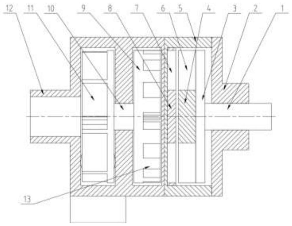
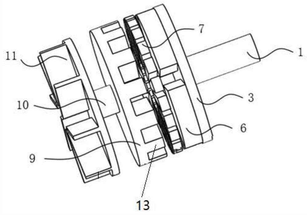
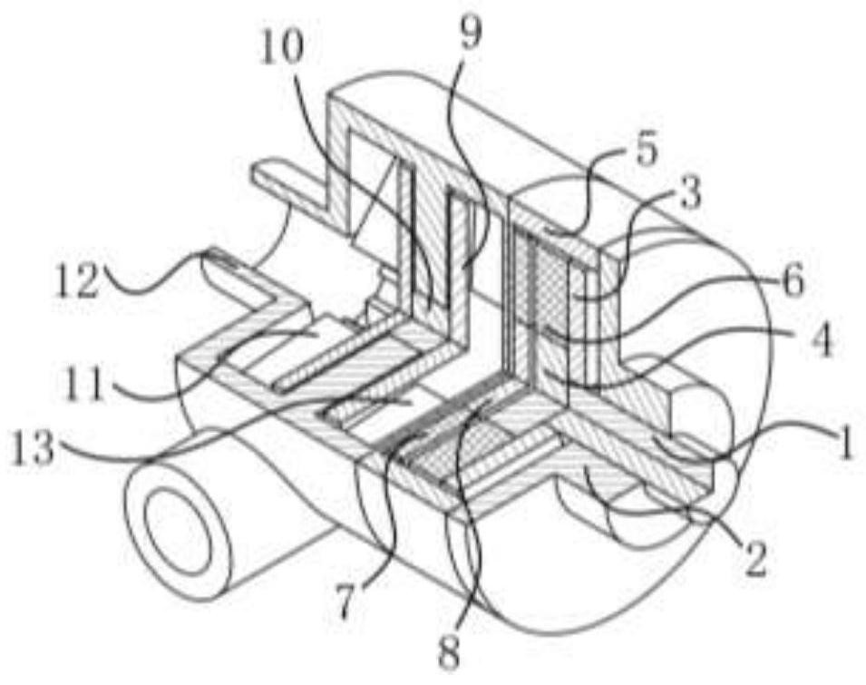
[0054] A magnetic pump with adjustable magnetic field, such as Figure 1~3 As shown, it includes a cylindrical back iron 3, a cylindrical output rotor 9, an end support 4, a fixed support 8, an input shaft 1, an input shaft end cover 2, an input housing 5, an output shaft 10, and an impeller 11 (such as Figure 7 shown) and the output end housing 12, the end face a of the back iron 3 is opposite to the end face b of the output rotor 9, the end face bracket 4 is fixed on the end face a of the back iron 3, the fixing bracket 8 is fixed in the magnetic pump of the magnetic adjustment type, and the back The end face of the iron 3 facing away from the output rotor 9 is vertically connected to the input shaft 1, the back iron 3 is coaxial with the input shaft 1, the end face of the output rotor 9 facing away from the back iron 3 is connected to one end face of the output shaft 10, and the other end face of the output shaft 10 The end surface is connected to the impeller 11, and the ...


PUM


Abstract

The invention relates to a magnetism-adjusted magnetic pump. The magnetism-adjusted magnetic pump comprises a cylindrical back iron and an output rotor which are coaxially arranged; an end surface a of the back iron is opposite to an end surface b of the output rotor; an input end permanent magnet is fixed on the end surface a of the back iron; multiple pairs of fan-shaped block type convex pole irons with the same sizes and uniformly distributed around the periphery of the center axis of the output rotor are fixed on the end surface b of the output rotor; a fixed end permanent magnet fixed inthe magnetism-adjusted magnetic pump is arranged between the back iron and the output rotor; the input end permanent magnet consists of multiple pairs of permanent magnets I; the fixed end permanentmagnet consists of multiple pairs of permanent magnets II; all the permanent magnets I or II are fan-shaped blocks uniformly distributed around the center axis of the back iron; magnetization directions of the adjacent permanent magnets I or II are opposite; and the convex pole number of the convex pole irons is equal to the pole pair number sum of the permanent magnets I and the permanent magnetsII. The magnetism-adjusted magnetic pump is simple in structure, and effectively solves the problems of wear of an isolation sleeve and low output torque due to high coaxiality requirements in a traditional magnetic pump.

Description

technical field [0001] The invention belongs to the technical field of magnetic force coupling drive, relates to a magnetic modulation type magnetic force pump, in particular to a new type of magnetic force pump which utilizes the principle of magnetic modulation and provides driving torque through the magnetic force coupling between permanent magnets. Background technique [0002] A magnetic pump is a device that uses the principle of magnetic coupling to drive a rotating body such as an impeller to transport fluid media. The magnetic pump in the prior art is mainly composed of an outer magnetic rotor, an inner magnetic rotor and a non-magnetic isolation sleeve, and the inner and outer magnetic rotors are axially coupled structures, and the rotation of the outer magnetic rotor drives the inner magnetic rotor to rotate synchronously. The inner magnetic rotor further drives the impeller to rotate, thereby realizing the pumping of the fluid. [0003] Most of the magnetic pump...

Claims


Application Information

Patent Timeline
Patent Type & Authority Patents(China)
IPC IPC(8): F04D13/06F04D29/66H02K49/10
CPCF04D13/024F04D13/027F04D13/06F04D29/669H02K49/108
Inventor 吴鹏朱姿娜
Owner SHANGHAI UNIV OF ENG SCI
Learn More