
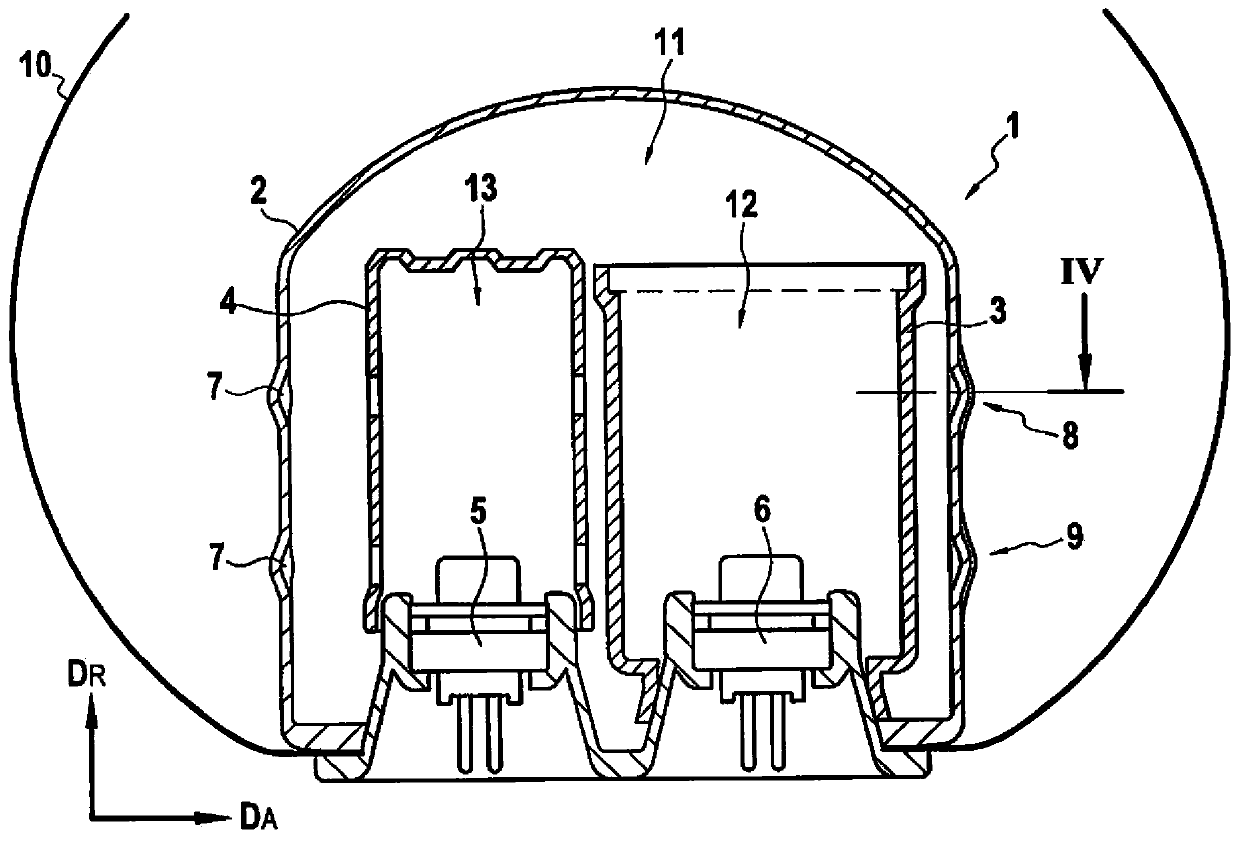
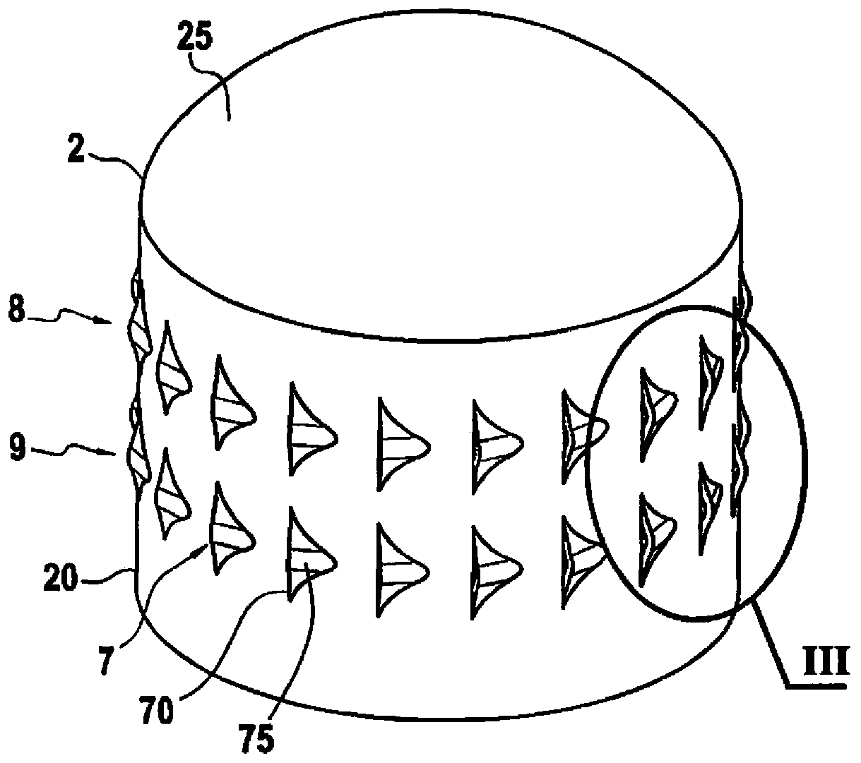
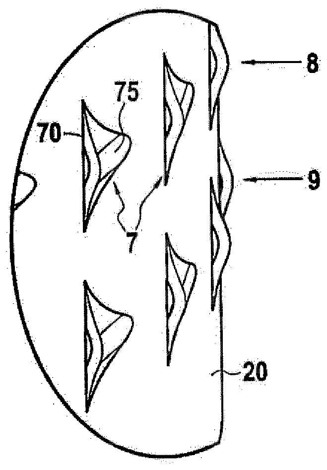
Pyrotechnical gas generator for an airbag.

一种气体发生器、烟火的技术,应用在车辆安全安排、行人/乘员安全布置、运输和包装等方向,能够解决不足以满足过滤装置等问题

Active Publication Date: 2020-02-04
SMART PALLET (SUZHOU) TECH CO LTD
View PDF5 Cites 0 Cited by
  • Summary
  • Abstract
  • Description
  • Claims
  • Application Information

AI Technical Summary

Problems solved by technology

[0010] However, these components alone are not sufficient to meet all the requirements that allow the removal of filter devices in pyrotechnic gas generators designed for use in airbags

Method used


Image

  • Pyrotechnical gas generator for an airbag.
  • Pyrotechnical gas generator for an airbag.
  • Pyrotechnical gas generator for an airbag.

Examples


Embodiment Construction

[0034] The present invention will be described with reference to particular embodiments and with reference to certain drawings but the invention is not limited thereto but only by the claims. The drawings described are only schematic and non-limiting. In the drawings, the size of some of the elements may be exaggerated and not drawn on scale for illustrative purposes. When the term "comprising" is used in the present description and claims, it does not exclude other elements or steps. Where an indefinite or definite article is used referring to a singular noun eg "a" or "an", "the", this includes a plural of that noun unless something else is specifically stated.

[0035] The term "comprising" used in the claims should not be interpreted as being restricted to the means listed thereafter, it does not exclude other elements or steps. Therefore, the scope of the expression "apparatus comprising devices A and B" should not be limited to an apparatus consisting of parts A and B ...


PUM


Abstract

A pyrotechnical gas generator (1) comprising at least one pyrotechnical charge, at least one ignitor (5, 6), and a cylindrical casing (2) enclosing said at least one charge and said at least one ignitor (5, 6), said cylindrical casing (2) having an axial direction (DA) and a radial direction (DR) and comprising an annular wall (20) extending along said axial direction (DA) of said casing (2), andgas ejection holes (7) arranged on said annular wall (20). Each gas ejection hole (7) extends in a output plan (P) forming a non-zero angle (a) with a tangential plan (T) which is tangent to said annular wall (20) at said gas ejection hole (7).

Description

technical field [0001] The present invention relates to an inflator, and in particular to a pyrotechnic gas generator designed to inflate an air bag of an air bag. The invention also relates to an airbag arrangement having such an inflator. Background technique [0002] An inflator for an airbag device for a passenger seat generally includes: a cylindrical case having holes for discharging gas on its peripheral surface; a propellant filled in the case; (evolution) supercharger; an electrical igniter for igniting the supercharger; and an auto-ignition material having an ignition temperature lower than that of the supercharger. Housings are usually made of steel or stainless steel. [0003] Current nozzles in inflators for delivering gas jets are usually circular holes made in a steel housing, sealed by a membrane and, for frontal disc inflators, typically have a diameter between 2mm and 4mm. The number of holes is usually between 4 and 16. As gas is generated from the pro...

Claims


Application Information

Patent Timeline
Patent Type & Authority Applications(China)
IPC IPC(8): B60R21/264
CPCB60R21/264B60R2021/26029B60R2021/2642
Inventor F·马林C·贝尼兰
Owner SMART PALLET (SUZHOU) TECH CO LTD
Features
  • Generate Ideas
  • Intellectual Property
  • Life Sciences
  • Materials
  • Tech Scout
  • Unparalleled Data Quality
  • Higher Quality Content
  • 60% Fewer Hallucinations
Learn More