
Three-ring fire valve core

A valve core and ring fire technology, which is applied to multi-way valves, valve devices, cocks including cut-off devices, etc. Improved safety and improved sealing effect

Inactive Publication Date: 2019-03-19
佛山市宇煜五金有限公司
View PDF8 Cites 0 Cited by
  • Summary
  • Abstract
  • Description
  • Claims
  • Application Information

AI Technical Summary

Problems solved by technology

[0003] The existing gas stove regulating spool generally has one inlet and one outlet or one inlet and two outlets, with only one air inlet and one or two independent air outlet channels, resulting in a smaller output airflow and lower discharge power of the gas stove. It is difficult to fully meet the needs of the market for hot and stir-frying, and because the general gas stove regulating valve core has only one or two independent air outlet channels, the adjustment range of the gas stove is small and the adjustment accuracy is low
[0004] A gas valve core disclosed in the Chinese Utility Model Patent Application Publication No. CN206708538U. Although the gas valve core is provided with a slag groove for collecting chips, the flame size of the inner ring fire and the outer ring fire can be adjusted independently. It is only necessary to set the outer ring fire channel and the inner ring fire channel inside the valve body, and no additional transition air channel is required, which facilitates the simplification of the valve body structure. However, the ventilation structure of the gas valve core is still a one-in-two-out structure , can only be used for household gas stoves, it is difficult to apply to commercial gas, and has the disadvantages of small output airflow and low discharge power

Method used


Image

  • Three-ring fire valve core
  • Three-ring fire valve core
  • Three-ring fire valve core

Examples


Embodiment Construction

[0030] The following will clearly and completely describe the technical solutions in the embodiments of the present invention with reference to the accompanying drawings in the embodiments of the present invention. Obviously, the described embodiments are only some, not all, embodiments of the present invention.

[0031] In the description of the present invention, unless otherwise stated, the meaning of "plurality" is two or more; the terms "upper", "lower", "left", "right", "inner", "outer" , "front end", "rear end", "head", "tail", etc. indicate the orientation or positional relationship based on the orientation or positional relationship shown in the drawings, and are only for the convenience of describing the present invention and simplifying the description, rather than Nothing indicating or implying that a referenced device or element must have a particular orientation, be constructed, and operate in a particular orientation should therefore not be construed as limiting ...


PUM


Abstract

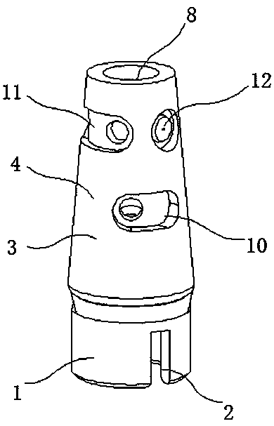
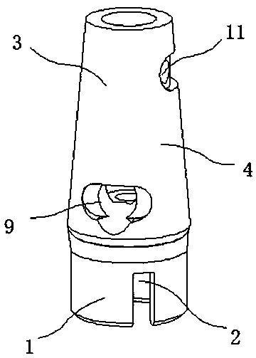
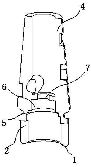
The invention discloses a three-ring fire valve core and relates to the technical field of gas stove adjusting valves. Specifically, the three-ring fire valve core comprises a fixing base and a conical vent valve core. A clamping and installing groove is formed in the middle of the fixing base. A sealing outer edge face is arranged on the outer surface of the conical vent valve core. The conical vent valve core is located above the fixing base. A connecting flange is arranged on the inner side of the conical vent valve core. A clamping flange is arranged above the connecting flange. A connecting hole is formed above the clamping flange. A gas inlet is connected above the connecting hole. A valve core lower portion gas outlet is formed in the middle of the conical vent valve core. Accordingto the three-ring fire valve core, total supply of fuel gas is achieved through the gas inlet, the whole device is installed on the fuel gas adjusting valve through the fixing base, fuel gas is supplied through the gas inlet in the bottom of the fixing base, the gas inlet is connected with the connecting hole in a communicating manner, meanwhile, the gas inlet and the fixing base are located on the same vertical line, and passing and supply efficiency of the fuel gas can be kept conveniently.

Description

technical field [0001] The invention relates to the technical field of gas stove regulating valves, in particular to a three-ring fire valve core. Background technique [0002] Gas stoves refer to kitchen utensils that use liquefied petroleum gas, artificial gas, natural gas and other gas fuels for direct fire heating. Gas stoves are mainly divided into liquefied gas stoves, gas stoves, and natural gas stoves. After entering the stove, it enters the burner through the adjustment of the gas valve, and at the same time mixes a part of the air. The mixed gas is ejected from the fire hole of the fire distributor and is ignited by the ignition device to form a flame. These flames are used to heat and place on the pot support. For cooking utensils, when the gas stove is working, the adjustment of the spool is the most important, which can control the switch of the gas stove and the size of the flame. [0003] The existing gas stove regulating spool generally has one inlet and one...

Claims


Application Information

Patent Timeline
IPC IPC(8): F16K11/083F16K5/02
CPCF16K5/0207F16K11/083
Inventor 李静师陈锡阳郭鹏飞黎伟杰
Owner 佛山市宇煜五金有限公司
Learn More