Flame-proof structure for stove topping pot

A pot-turning and flame-proof technology, which is applied to household stoves/stoves, incinerators, household stoves, etc., can solve problems such as the inability to discharge the smoke from the fire channel, the escape of flames and smoke, and the backflow of the fire channel.

Active Publication Date: 2020-04-14
张跃虎
View PDF8 Cites 0 Cited by
  • Summary
  • Abstract
  • Description
  • Claims
  • Application Information

AI Technical Summary

Problems solved by technology

However, in the process of inverting the pot, because the pressure adaptation of the circulation channel is destroyed, it is easy to cause the fire channel to flow backwards. pressure, so that the smoke in the fire channel cannot be discharged, and the flame and smoke escape outwards

Method used


Image

  • Flame-proof structure for stove topping pot
  • Flame-proof structure for stove topping pot
  • Flame-proof structure for stove topping pot

Examples


Embodiment 1

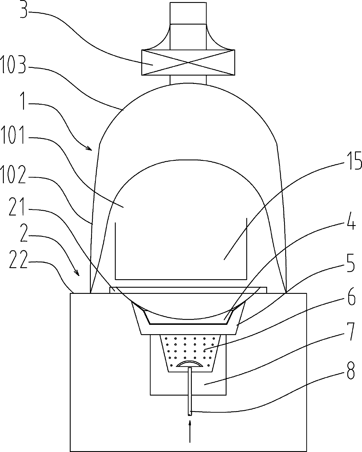
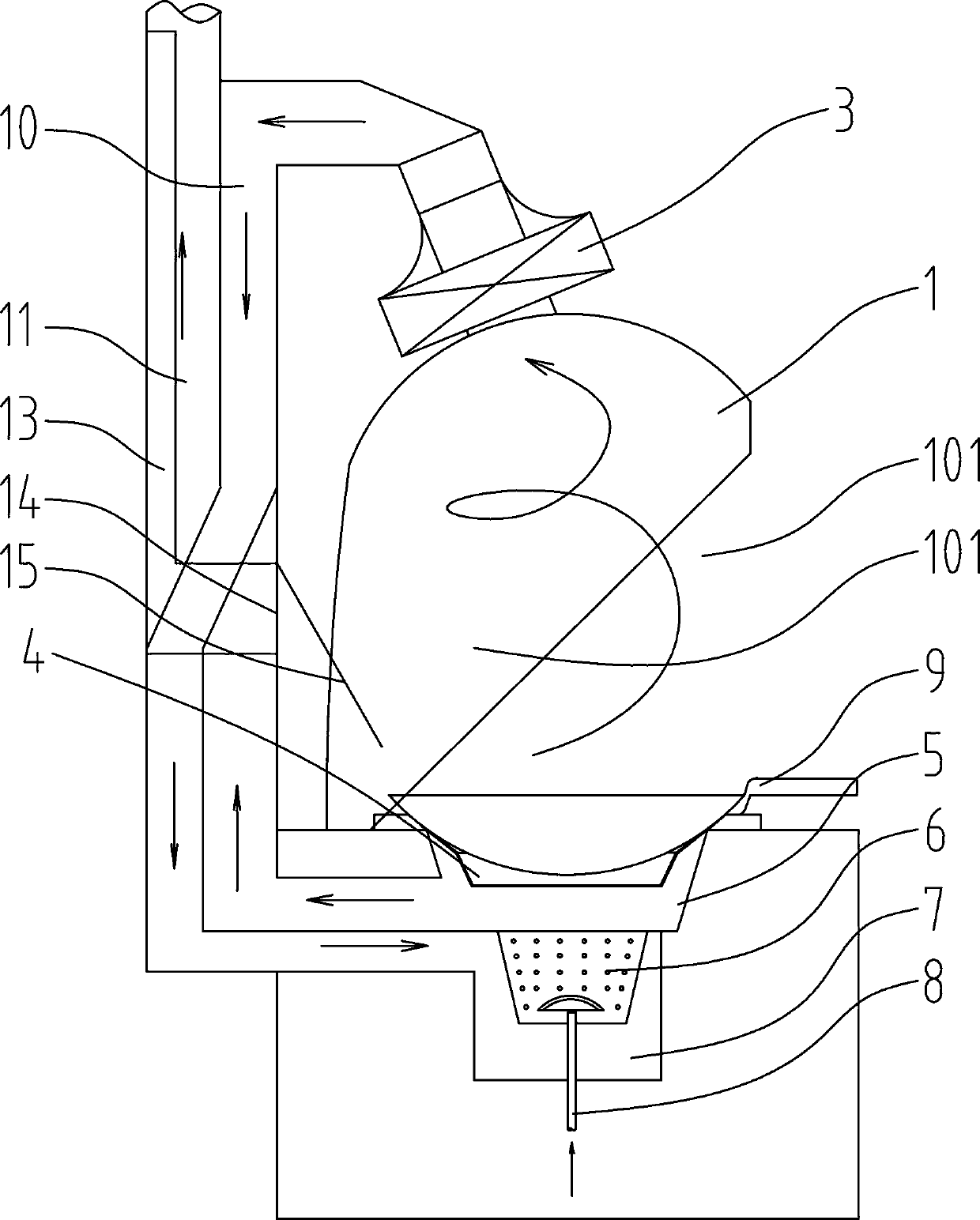
[0031] like Figures 1~3 Among them, a stove topping pot flameproof structure, comprising a stove body 2, a furnace is provided in the stove body 2, a smoke hood 1 is arranged above the furnace, a fire vent 14 is provided at the back of the smoke hood 1, and a fire vent 14 connected to the chimney. With this structure, during the process of the operator turning the pot, the flame ejected from the furnace is attracted by the fire vent 14, which will not affect the operator's operation.

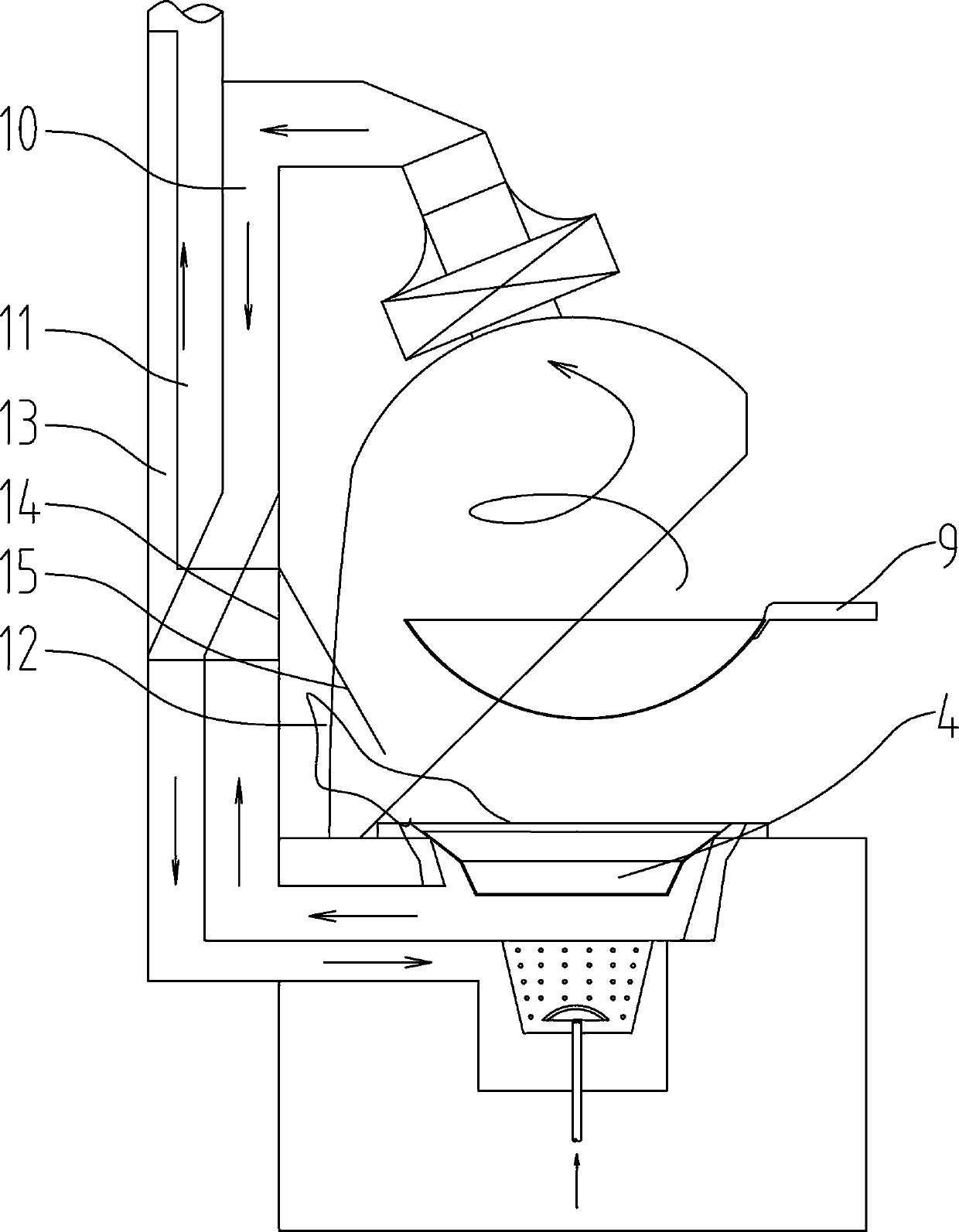
[0032] The preferred solution is as figure 2 , 3 Among them, a fire deflector 15 inclined downward is provided above the fire vent 14;

[0033] The bottom of the fire guide plate 15 is located near the upper end of the furnace, away from the operator's side. With this structure, it is convenient to guide the flame into the fire vent 14, and it is possible to separate the flame from the oil fume, so as to avoid the untreated discharge of the oil fume.

Embodiment 2

[0035] On the basis of the above examples, the preferred scheme is as Figures 1~5 Among them, a flame guide device 4 is provided between the top of the furnace and the pot 9, the space between the furnace hearth and the flame guide device 4 communicates with the chimney, and a recess 42 is provided on the flame guide device 4, and the recess 42 is connected to the pot 9. A cavity structure is formed between the bottoms, and a fire hole 43 or a fire grill 45 is provided in the recessed part 42 . With this structure, the cavity structure between the recessed portion 42 and the bottom of the pot 9 maintains a positive pressure all the time, and the flame can be prevented from erupting toward the operator, thereby overcoming the influence of the pot upset on the operator. It should be noted that in the prior art, there is also a scheme of controlling the gas output to make the flame smaller when the pot is turned upside down, but this scheme makes it difficult to realize the oper...

Embodiment 3

[0044] On the basis of the above examples, the preferred scheme is as Figures 1~3 Among them, the hood 1 is provided with a back side and a side wall 102 of the hood, the back of the hood 1 is connected with the back of the stove body 2, the top of the hood 1 is provided with a hood dome 103, and the top of the hood 103 is The position is connected with exhaust fan 3. With this structure, when the exhaust fan 3 is started, the oxygen supply air enters into the fume hood 1 from the air inlet 101 in the atmospheric environment under negative pressure conditions. Greatly improve the efficiency of oil fume collection.

[0045] In a preferred solution, the distance between the side wall 102 of the fume hood and the stove body 2 is 0-40 cm. Specifically, the distance between the bottom of the side wall 102 of the plane, arc or nearly circular surface of the smoke hood 1 and the stove body table 22 of the stove body 2 is 0-40 cm, preferably 0-20 cm, and more preferably 0 to 10 cm...


PUM


Abstract

The invention provides a cooking range wok tossing flame-resistant structure. The cooking range wok tossing flame-resistant structure comprises a cooking range body. The cooking range body is internally provided with a combustion chamber. A smoke hood is arranged above the combustion chamber. The back side of the smoke hood is provided with a flame release port communicating with a chimney. A flame guide plate inclined downwards is arranged above the flame release port. The bottom of the flame guide plate is located in the position the side close to the upper end of the combustion chamber andfar away from an operator. Flames can be sucked by the flame release port arranged on the back side of the smoke hood during wok tossing to prevent flame jet from affecting normal operation of the operator and affecting collection of lampblack. In an optimized scheme, through a flame guide device arranged between the upper portion of the combustion chamber and a wok, the problem that the pressureadaptability of a lampblack circulating passage is destroyed during wok tossing is solved. In the wok tossing process, flames cannot be violently jetted upwards and outwards, and collection of lampblack cannot be affected.

Description

technical field [0001] The invention relates to the field of household or commercial stoves, in particular to a flame-proof structure for cooking stoves that does not spray out a large amount of flames and affect the collection of oil fumes when the cooker is turned over. Background technique [0002] Recently, the public is very disgusted with the oily fumes produced by catering stoves. In homes or communities, the exhaust of oily fumes produced by household or commercial stoves is a hot spot for complaints. And the smoke exhaust ventilator that adopts indoor is usually difficult to meet the user's requirement. [0003] Existing range hoods commonly used have following several structures, 1, up-pumping type, such as the cooker range hood recorded in Chinese patent document CN1246641C, adopts an upper cover body, blower fan is set on the upper cover body, and oil fumes are collected by the cover body , and discharged from the fan. But although various improvements have bee...

Claims


Application Information

Patent Timeline
Patent Type & Authority Patents(China)
IPC IPC(8): F24C15/20F23G7/06
CPCF23G7/065F24C15/2071
Inventor 张跃虎
Owner 张跃虎
Why Eureka
Try Eureka