Fixed installation structure of drainage pipeline

A technology for installing structures and drainage pipes, which is applied in the direction of pipe brackets, pipe components, pipes/pipe joints/pipe fittings, etc., and can solve the problems of uncoordinated expansion and contraction of drain pipes, low installation efficiency, and extrusion damage of drain pipes, etc.

Active Publication Date: 2020-02-07
江苏华淼电子科技有限公司
View PDF8 Cites 12 Cited by
  • Summary
  • Abstract
  • Description
  • Claims
  • Application Information

AI Technical Summary

Problems solved by technology

[0002] At present, when carrying out rainwater drainage for buildings, it is necessary to divert the water through conduits to drain the accumulated water at the top to the lower level. The length of the conduits varies with the height of the building. Fixed, the pipeline clamp is a ring structure. During installation, the operator first nails the pipeline clamp fixing nails into the wall. The installation efficiency is low, which increases the difficulty of the operation, and the drainage pipe cannot be expanded and contracted when it is heated and contracted, and it is easy to drain the water. tube crush damage
[0003] Publication No. CN206563132U discloses a construction drainage pipe installation structure, the main points of the technical solution are to include a wall, the outside of the wall is provided with a drainage pipe, the outer wall of the drainage pipe is provided with a fixing ring, the wall is provided with a mounting seat, and the mounting seat and Elastic telescopic rods are arranged between the fixing rings, holes are arranged on the wall, and fixing parts fixed in the openings are arranged on the mounting base. The fixing parts include fixing screws, threaded sleeves fitted outside the fixing screws, and fixing screws One end is a tapping thread, and the outer wall of the screw sleeve is distributed with a number of elastic barbs inclined towards the opening of the hole. The screw sleeve runs through the mounting seat and cooperates with the thread of the mounting seat. The above scheme is also fixed for the drainage pipe. Visible Fixed installation of drainage pipes is common in the industry. When the above-mentioned building drainage pipe installation structure is installed, the drainage pipes are fixed by nuts and screws, which makes the installation efficiency low and increases the difficulty of operation.

Method used


Image

  • Fixed installation structure of drainage pipeline
  • Fixed installation structure of drainage pipeline
  • Fixed installation structure of drainage pipeline

Examples


Embodiment 1

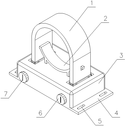
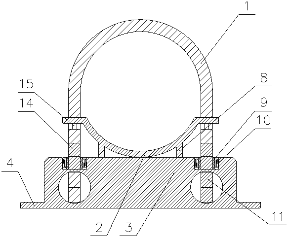
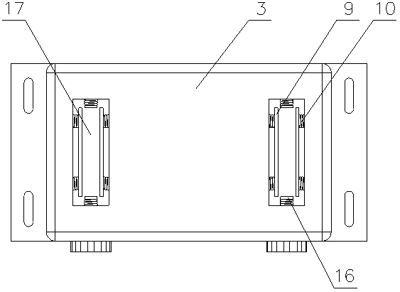
[0019] A fixed installation structure of a drainage pipe in the present invention is realized in this way. It is composed of a main device and a fixing device. The main device is composed of a fixing seat (3), a connecting plate (4), a connecting groove (5) and a fixing groove (17). The connecting plate (4) is fixedly placed at the bottom of the fixing seat (3), the length of the connecting plate (4) is longer than that of the fixing seat (3), and the connecting plate (4) has a plurality of connecting grooves near one end ( 5), the connecting plate (4) has a plurality of connecting grooves (5) near the other end, and two fixing grooves (17) are symmetrically opened on the top of the fixing base (3), and the fixing grooves (17) It is a rectangular slot, and the fixing device consists of a main fixing plate (1), an auxiliary fixing plate (2), a knob (6), an indicator groove (7), a limit block (8), a long splint (9), a spring (10), The rotating magnet (11), the fixed magnet (14),...

Embodiment 2

[0024] The difference between this embodiment and Embodiment 1 is: the rotating shaft is provided with a plurality of sockets (13) at equal angles, and a limit screw (19) is additionally provided on the fixing base (3), and the limit screw One end of (19) passes through the fixing seat (3) and is placed in the socket (13); when in use, it can prevent the main fixing plate (1) from falling off due to the automatic reset of the knob (6).

[0025] The chute (15) is a cross-shaped groove, and the insert block is a cross-shaped structure, which can make the movement of the insert block in the chute (15) more stable.

[0026] The main fixed plate (1) is adsorbed and fixed through the cooperation of the rotating magnet (11) and the fixed magnet (14), and the purpose of corresponding expansion and contraction is achieved when the drain pipe expands with heat and contracts with cold through the cooperation of the slider and the chute (15). .


PUM


Abstract

The invention discloses a fixed installation structure of a drainage pipeline. In the fixed installation structure, a main fixing plate is adsorbed and fixed through cooperation of a rotating magnet and a fixed magnet, and a sliding block and a sliding groove are matched and slid to correspondingly stretch and contract when the drainage pipeline expands in hot and contracts in cold. A rotary knobis rotated to change the magnetic pole direction of the rotating magnet to be matched with the fixed magnet to fix the drainage pipe, screw fixing is not needed, and convenience and rapidness are achieved. The fixed installation structure is characterized in that a connecting plate is fixedly arranged at the bottom of a fixing seat, the length of the connecting plate is larger than that of the fixing seat, a plurality of connecting grooves are formed in the position, close to one end, of the connecting plate, a plurality of connecting grooves are formed in the position, close to the other end,of the connecting plate, two fixing grooves are symmetrically formed in the top of the fixing seat, the fixing grooves are rectangular grooves, and two long clamping plates are arranged in the fixinggrooves and fixedly connected with the two sides of the fixing grooves correspondingly through springs.

Description

technical field [0001] The invention relates to a fixed installation structure of a drainage pipe, which relates to a structure for fixed installation of a drainage pipe, and belongs to the field of construction engineering. In particular, it relates to a fixed installation structure in which the main fixed plate is adsorbed and fixed through the cooperation of the rotating magnet and the fixed magnet, and the sliding block and the chute cooperate to slide when the drain pipe expands with heat and contracts with cold. Background technique [0002] At present, when carrying out rainwater drainage for buildings, it is necessary to divert the water through conduits to drain the accumulated water at the top to the lower level. The length of the conduits varies with the height of the building. Fixed, the pipeline clamp is a ring structure. During installation, the operator first nails the pipeline clamp fixing nails into the wall. The installation efficiency is low, which increas...

Claims


Application Information

Patent Timeline
Patent Type & Authority Applications(China)
IPC IPC(8): F16L55/035F16L3/10
CPCF16L3/10F16L55/035
Inventor 不公告发明人
Owner 江苏华淼电子科技有限公司
Why Eureka
Try Eureka