
Optical element, lens, camera and electronic device

A technology of optical components and driving components, applied in the optical field, can solve the problems of image underexposure and overexposure

Active Publication Date: 2020-02-07
GUANGDONG OPPO MOBILE TELECOMM CORP LTD
View PDF8 Cites 1 Cited by
  • Summary
  • Abstract
  • Description
  • Claims
  • Application Information

AI Technical Summary

Problems solved by technology

The image quality captured by the camera is related to many factors. For example, it can be understood that under certain other conditions, when the amount of light entering the camera is large, the image captured by the camera is prone to overexposure. , the image captured by the camera is prone to underexposure

Method used


Image

  • Optical element, lens, camera and electronic device
  • Optical element, lens, camera and electronic device
  • Optical element, lens, camera and electronic device

Examples


Embodiment Construction

[0028] Embodiments of the present application are described in detail below, examples of which are illustrated in the accompanying drawings, wherein the same or similar reference numerals refer to the same or similar elements or elements having the same or similar functions throughout. The embodiments described below with reference to the accompanying drawings are exemplary, only used to explain the present application, and should not be construed as a limitation on the present application. The following disclosure provides many different embodiments or examples for implementing different structures of the present application. To simplify the disclosure of the present application, the components and arrangements of specific examples are described below. Of course, they are only examples and are not intended to limit the application. Furthermore, this application may repeat reference numerals and / or reference letters in different instances for the purpose of simplicity and cla...


PUM


Abstract

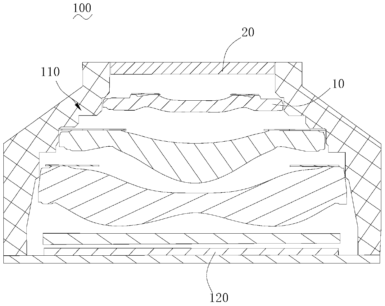
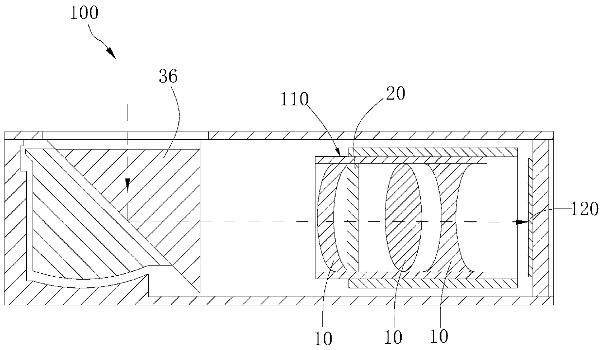
The application discloses an optical element, a lens, a camera and an electronic device, and the optical element comprises the following parts of a first light-transmitting wall; a second light-transmitting wall opposite to the first light-transmitting wall; and a movable member connecting the first light-transmitting wall and the second light-transmitting wall and defining a light-passing window,wherein the movable member surrounds the first light-transmitting wall and the second light-transmitting wall to form a closed chamber, which is used for containing light-transmitting liquid; the movable member can move relative to the first light-transmitting wall to change the curvature of the first light-transmitting wall and / or the second light-transmitting wall through the light-transmittingliquid, and to change the size of the light-transmitting window to change the light-transmitting amount of the optical element. In this way, the movable member can move relative to the first light-transmitting wall to change the curvature of the first light-transmitting wall and / or the second light-transmitting wall, thereby changing the refractive power of the optical element. In addition, the size of the light-transmitting window can be changed during the movement of the movable member, so that the light flux of the optical element can be changed.

Description

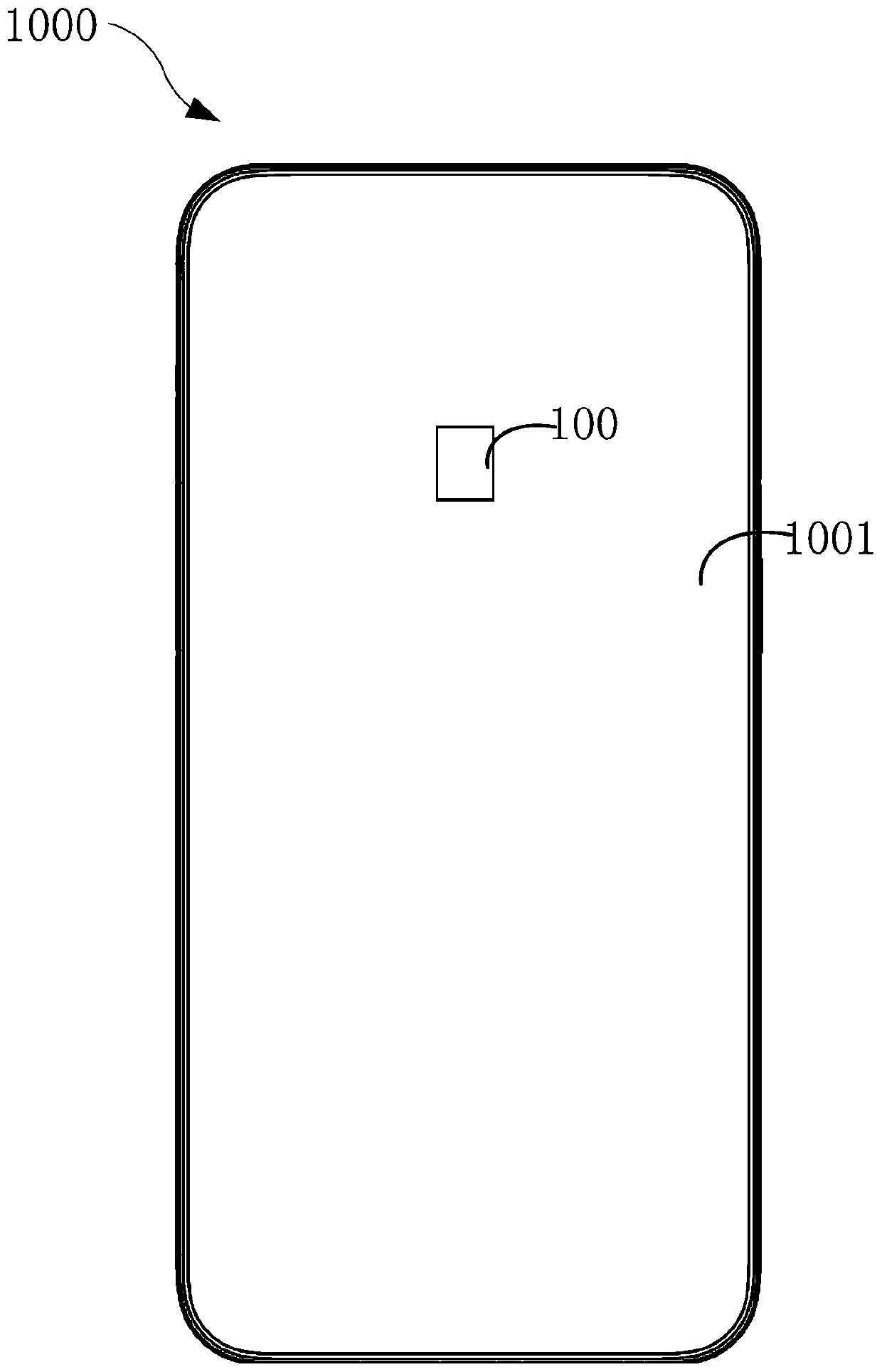
technical field [0001] The present application relates to the field of optical technology, and in particular, to an optical element, a lens, a camera, and an electronic device. Background technique [0002] In the related art, a camera of an electronic device such as a mobile phone can be exposed through an opening opened on the back cover or the display screen. The quality of the image captured by the camera is related to many factors. For example, it can be understood that under certain other conditions, when the amount of light entering the camera is large, the image captured by the camera is prone to overexposure. When the amount of light entering the camera is small , the image captured by the camera is prone to underexposure. Therefore, how to improve the image quality captured by the camera becomes the direction of camera improvement. SUMMARY OF THE INVENTION [0003] The present application provides an optical element, a lens, a camera and an electronic device. ...

Claims


Application Information

Patent Timeline
Patent Type & Authority Applications(China)
IPC IPC(8): G02B3/14G02B26/00G02B7/02G03B17/12H04N5/225
CPCG02B3/14G02B26/004G02B7/021G03B17/12H04N23/55
Inventor 周彦汝
Owner GUANGDONG OPPO MOBILE TELECOMM CORP LTD
Learn More