Self-locking device for linear actuator and linear actuator

A technology of linear actuator and self-locking device, applied in the direction of transmission device, brake type, legs of general furniture, etc., can solve problems such as insufficient self-locking force

Active Publication Date: 2020-02-11
ZHEJIANG JIECHANG LINEAR MOTION TECH
View PDF9 Cites 4 Cited by
  • Summary
  • Abstract
  • Description
  • Claims
  • Application Information

AI Technical Summary

Problems solved by technology

At present, most of the self-locking functions of this type of lifting column on the market are realized by the brake torsion spring. Self-locking structure, its self-locking force is relatively insufficient

Method used


Image

  • Self-locking device for linear actuator and linear actuator
  • Self-locking device for linear actuator and linear actuator
  • Self-locking device for linear actuator and linear actuator

Examples


Embodiment 1

[0033] like Figure 1 to Figure 5 As shown, the application of the self-locking device in the linear actuator is shown. There are many types of linear actuators, such as lifting columns, such as electric push rods, etc. The self-locking device of this embodiment is specifically used in a lift On the column, the lifting column is usually used for electric lifting table, so it is also called lifting table leg. As far as the lifting table is concerned, the driving motor 11 is used to drive up and down under normal conditions, but once the driving motor 11 does not work, or is in an abnormal power failure, the lifting column itself needs to have a certain self-locking function to prevent the desktop. The problem of automatic lowering occurs when a large load is applied, so the lifting column of the existing electric lifting table usually needs to have a self-locking device, and the self-locking device of the existing lifting column is usually a torsion spring brake.

[0034] In t...

Embodiment 2

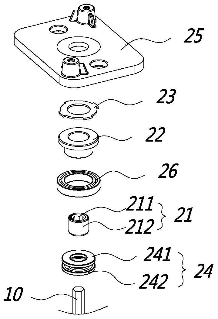
[0045] like Image 6 and Figure 7 As shown, the difference between this embodiment and the first embodiment is that in the first embodiment, the frictional force is generated between the friction member 23 and the friction collar 22 by means of end contact, while in this embodiment, the frictional member 23 Between the friction collar 22 and the friction collar 22, the frictional force is generated by the circumferential side part of the friction collar 22 and the friction piece 23.

[0046] In this embodiment, the friction member 23 includes a friction outer ring installed in the support base 25. In this embodiment, since the support base 25 includes a base inner cavity 251, the friction outer ring can be used with the inner cavity of the base 251. The wall of the cavity 251 is installed by interference fit. Of course, in other embodiments, other fixed connection methods can be used. The friction outer ring is sleeved outside the friction collar 22, and the friction outer r...

Embodiment 3

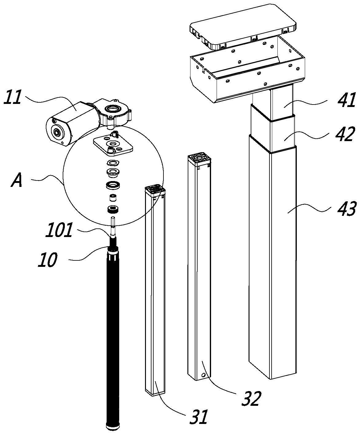
[0051] same as Figure 1 to Figure 5 As shown, this embodiment is a linear actuator. As mentioned above, the linear actuator of this embodiment is preferably a lifting column. This embodiment includes a first sleeve 31, a second sleeve 32, a rotating The screw 10, the drive nut, and the drive motor 11. The drive motor 11 drives the rotating screw 10 to rotate. When the rotating screw 10 rotates, it drives the drive nut to move axially, and the drive nut moves to drive the first sleeve 31 and the second sleeve 32. Relative scaling occurs.

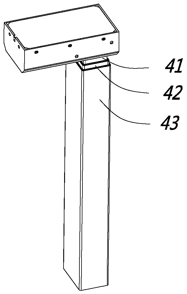
[0052] The lifting column in this embodiment is preferably a three-section lifting column, wherein the first sleeve 31, the second sleeve 32, the rotating screw 10, the transmission nut, the driving motor 11, etc. constitute a transmission assembly, the lifting and lowering The upright column also includes an inner tube 41, a middle tube 42, and an outer tube 43, and the transmission assembly drives the inner tube 41, the middle tube 42, an...


PUM


Abstract

The invention discloses a self-locking device for a linear actuator, and belongs to the field of linear actuation equipment. The self-locking device includes a one-way bearing and a friction collar, and further includes a friction member for being matched with the friction collar. The one-way bearing includes an inner ring and an outer ring, and the inner ring is used for sleeving a rotary screw rod of the linear actuator. The friction collar is connected with the outer ring. When the rotary screw rod rotates in the forward direction, the outer ring does not rotate. When the rotary screw rod rotates in the reverse direction, the outer ring, the inner ring and the friction collar rotate synchronously, and the friction collar is in contact with the friction member to generate friction force.The invention further discloses the linear actuator adopting the self-locking device. The self-locking device for the linear actuator has the advantage that the self-locking ability of the linear actuator can be increased.

Description

【Technical field】 [0001] The invention relates to a self-locking device of a linear actuator and a linear actuator, belonging to the field of linear actuating equipment. 【Background technique】 [0002] Linear actuators are currently widely used in various fields, including electric lift tables, electric beds, electric sofas, etc. The structure of this linear actuator usually includes a drive motor, a rotating screw, a transmission nut, and the drive motor drives the rotating wire. When the rod rotates, the rotating screw drives the drive nut to move axially, and the drive nut can be connected to the drive object to achieve the drive purpose. [0003] Taking the electric lifting table as an example, the current electric lifting table includes a lifting column, and the lifting column includes a driving motor, a rotating screw, a transmission nut, and the transmission nut drives the pipe to rise or fall. Lock function, that is, when the motor is not running, the lifting column...

Claims


Application Information

Patent Timeline
Patent Type & Authority Applications(China)
IPC IPC(8): F16H25/24F16D63/00A47B91/02
CPCF16H25/24F16D63/00A47B91/02A47B9/20A47B9/04A47B2200/0054A47B2200/0056F16H2025/2084F16H25/2454F16D59/00F16D2127/004A47B2200/0059F16D63/008
Inventor 胡仁昌陆小健其他发明人请求不公开姓名
Owner ZHEJIANG JIECHANG LINEAR MOTION TECH
Why Eureka
Try Eureka