A positioning welding device for steel bars

A positioning welding and steel bar technology, applied in welding equipment, welding equipment, auxiliary devices, etc., can solve problems such as large space occupation, welding deviation, and non-compliance

Active Publication Date: 2021-05-07
赵若辰
View PDF7 Cites 0 Cited by
  • Summary
  • Abstract
  • Description
  • Claims
  • Application Information

AI Technical Summary

Problems solved by technology

[0002] In the field of construction, steel bars are an indispensable building material, and with the rapid development of the economy, the demand for steel bars in high-rise buildings has been greatly increased, and there are also high requirements for the quality of steel bars, and in the actual use process In the field, the steel bars used on site will be reprocessed according to the actual situation, that is, re-cut or lengthened. In the existing technology, the method of lengthening the steel bars is mostly manual welding, and the steel bars are connected and welded using welded joints. Manual hand support is required. During the processing, since the two ends are in the suspended position, the welding deviation or inclination may occur. After welding, the steel bars on both sides are not on the same level, which will cause subsequent use. Failure to meet the standard will affect the quality of the building. Although some welding devices are equipped with mounting devices on both sides, due to the long length of steel bars, the mounting devices installed on the device are relatively long and occupy a large space, which is very inconvenient during use and affects Efficiency in use; therefore, it is very necessary to provide a steel bar positioning welding device with good positioning effect, convenient welding and simple operation

Method used


Image

  • A positioning welding device for steel bars
  • A positioning welding device for steel bars
  • A positioning welding device for steel bars

Examples


Embodiment 1

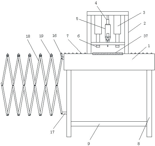
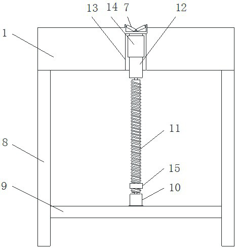
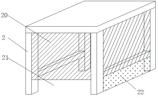
[0024] like Figure 1-7As shown, a steel bar positioning welding device includes a device body 1, a support frame 2 is arranged in the center of the upper part of the device body 1, and a hydraulic cylinder 3 is fixed inside the support frame 2. The number of the hydraulic cylinders 3 is Two, a welding torch 5 is arranged between the hydraulic cylinders 3, the welding torch 5 is connected with the top of the support frame 2 through the slideway 4, the lower end of the hydraulic cylinder 3 is provided with a pressure head, and the lower part of the hydraulic cylinder 3 is on the device body 1 A support plate 37 is provided, the upper surface of the device body 1 is also provided with an idler A7, the lower part of the device body 1 is provided with legs 8, and a fixing rod 9 is arranged between the legs 8, and the fixing rod 9 A servo motor 10 is fixedly arranged on the upper part, the power end of the servo motor 10 is connected with a screw rod 11 , and the upper end of the s...

Embodiment 2

[0027] like Figure 1-7 As shown, a steel bar positioning welding device includes a device body 1, a support frame 2 is arranged in the center of the upper part of the device body 1, and a hydraulic cylinder 3 is fixed inside the support frame 2. The number of the hydraulic cylinders 3 is Two, a welding torch 5 is arranged between the hydraulic cylinders 3, the welding torch 5 is connected with the top of the support frame 2 through the slideway 4, the lower end of the hydraulic cylinder 3 is provided with a pressure head, and the lower part of the hydraulic cylinder 3 is on the device body 1 A support plate 37 is provided, the upper surface of the device body 1 is also provided with an idler A7, the lower part of the device body 1 is provided with legs 8, and a fixing rod 9 is arranged between the legs 8, and the fixing rod 9 A servo motor 10 is fixedly arranged on the upper part, the power end of the servo motor 10 is connected with a screw rod 11 , and the upper end of the ...


PUM


Abstract

The invention relates to a steel bar positioning welding device. A supporting frame is arranged in the center of the upper part of the device body. A hydraulic cylinder is fixed inside the supporting frame. A welding torch is arranged between the hydraulic cylinders. The welding torch is connected to the top of the supporting frame through a slideway. There is a pressure head, a support plate is set on the device body under the hydraulic cylinder, and an idler roller A is also set on the upper surface of the device body, legs are set on the lower part of the device body, and fixing rods are arranged between the legs. The upper part is fixed with a servo motor, the power end of the servo motor is connected with a screw rod, the upper end of the screw rod is connected with the fixed column in rotation, the upper part of the fixed column is fixedly connected with the device body, the fixed column is also provided with a fixed ring, and the screw rod is provided with The movable ring is provided with an upper connecting piece on the fixed ring, and a lower connecting piece is arranged on the movable ring, the upper connecting piece and the lower connecting piece are connected with the telescopic frame, and a fixed buckle is provided at the hinge of the telescopic frame; the present invention has good positioning effect, welding Advantages of convenience and simple operation.

Description

technical field [0001] The invention relates to the technical field of steel bar welding, in particular to a steel bar positioning welding device. Background technique [0002] In the field of construction, steel bars are an indispensable building material, and with the rapid development of the economy, the demand for steel bars in high-rise buildings has been greatly increased, and there are also high requirements for the quality of steel bars, and in the actual use process In the field, the steel bars used on site will be reprocessed according to the actual situation, that is, re-cut or lengthened. In the existing technology, the method of lengthening the steel bars is manual welding, and the welding of the steel bars is welded. Manual hand support is required. During the processing, since the two ends are in the suspended position, the welding deviation or inclination may occur. After welding, the steel bars on both sides are not on the same level, which will cause subseq...

Claims


Application Information

Patent Timeline
Patent Type & Authority Patents(China)
IPC IPC(8): B23K31/02B23K37/04
Inventor 赵若辰赵方怡王红卫
Owner 赵若辰
Why Eureka
Try Eureka