
Valve element micrometric displacement testing device

A testing device and micro-displacement technology, applied in the direction of fluid pressure actuation device, fluid pressure actuation system testing, mechanical equipment, etc., can solve the problem of inability to design accurate guidance

Active Publication Date: 2017-05-03
BEIJING RES INST OF PRECISE MECHATRONICS CONTROLS +1
View PDF6 Cites 3 Cited by
  • Summary
  • Abstract
  • Description
  • Claims
  • Application Information

AI Technical Summary

Problems solved by technology

Due to the lack of these basic studies, empirical theories are mostly used for reference in the design of servo valves, which cannot form an accurate guidance for the design. Therefore, basic research on servo valves is required.

Method used


Image

  • Valve element micrometric displacement testing device
  • Valve element micrometric displacement testing device
  • Valve element micrometric displacement testing device

Examples


Embodiment Construction

[0019] The present invention will be described in further detail below in conjunction with the accompanying drawings and embodiments.

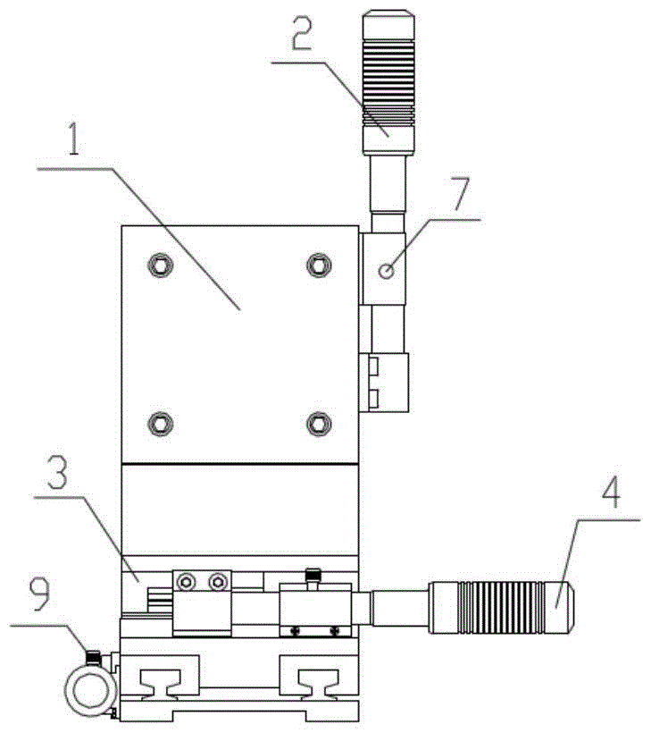
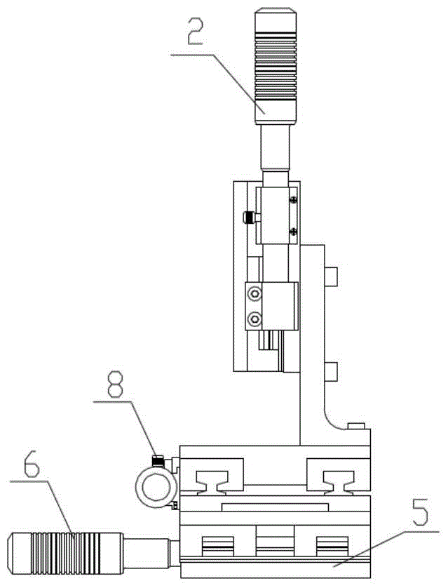
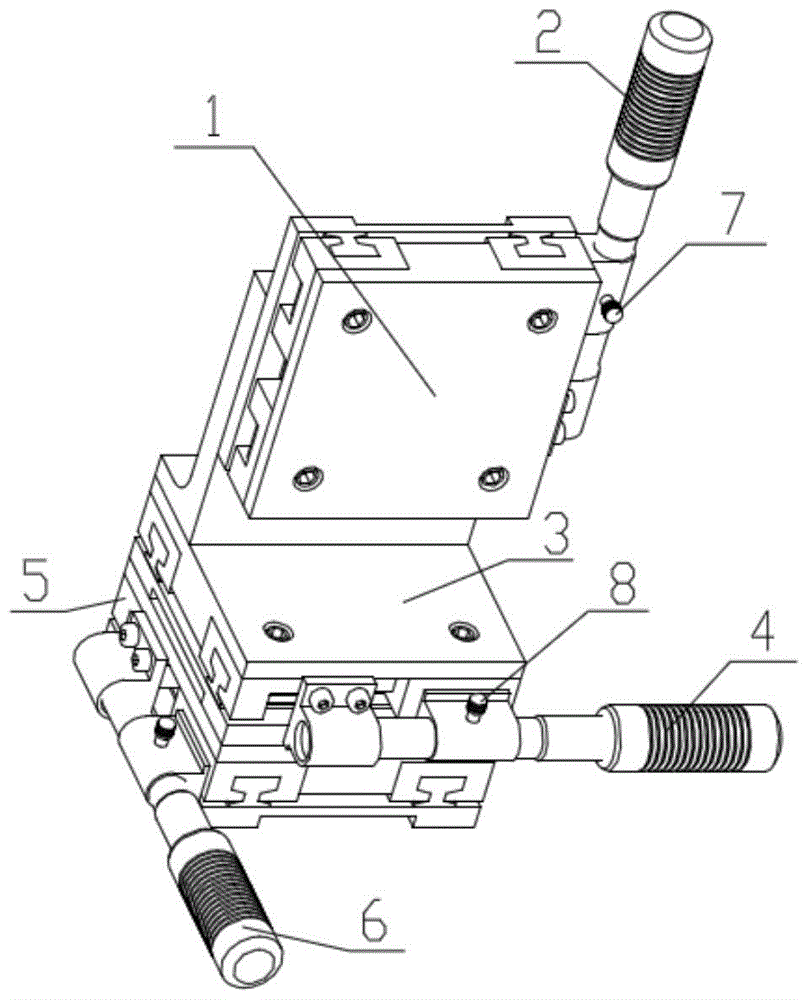
[0020] The present invention is a spool micro-displacement testing device, which comprises a Y-direction adjustment platform 5, an X-direction adjustment platform 3 located on the upper part of the Y-direction adjustment platform 5, a Z-direction adjustment platform 1 located on the upper part of the X-direction adjustment platform 3, and a Y-direction adjustment platform 1. The adjustment platform 5 can move along the Y direction; the X-direction adjustment platform 3 can move along the X direction; the Z-direction adjustment platform 1 can move along the Z direction.

[0021] The Y-direction adjustment platform 5 is a platform, including the Y support part of the lower part and the Y mobile part positioned at the upper part of the Y support part, the Y-direction adjustment device 6 adjusts the movement of the Y mobile part, and the Y-directio...


PUM


Abstract

The invention belongs to the field of testing, and particularly relates to a valve element micrometric displacement testing device. The device comprises a Y-direction adjusting platform, an X-direction adjusting platform fixedly located at one end of the Y-direction adjusting platform, and a Z-direction adjusting platform fixedly located at the other end, opposite to the Y-direction adjusting platform, of the X-direction adjusting platform, wherein the Y-direction adjusting platform can move in the Y direction, the X-direction adjusting platform can move in the X direction, and the Z-direction adjusting platform can move in the Z direction. According to the valve element micrometric displacement testing device, accurate and quantitative testing can be conducted on servo valve element micrometric displacement, and therefore a foundation is laid for studying valve element viscous damping coefficients and other power level parameters.

Description

technical field [0001] The invention belongs to the testing field, and in particular relates to a valve core micro-displacement testing device. Background technique [0002] The servo valve is the core control element of the servo mechanism. Its main function is to convert tiny milliwatt-level electrical signals into tens of kilowatts of hydraulic flow output, and control the swing angle of the servo mechanism through the closed-loop control system, so as to achieve the purpose of vector control of the missile flight state. [0003] The performance of the servo valve directly affects the performance of the servo system. At present, in the existing technology, there are many researches on the external characteristics of the servo valve, but there are relatively few basic researches on the changes of the external characteristics of the servo valve directly, such as the basic characteristics of the power stage spool of the servo valve, such as the viscosity of the spool Dampi...

Claims


Application Information

Patent Timeline
Patent Type & Authority Applications(China)
IPC IPC(8): F15B19/00
Inventor 王鹏仇立波陈琴王书铭
Owner BEIJING RES INST OF PRECISE MECHATRONICS CONTROLS
Learn More