Spring pin dismounting device

A dismantling device and spring pin technology, which is applied in the direction of hand-held tools and manufacturing tools, can solve the problems of difficult operation, high operator experience and technical requirements, and long time consumption, so as to achieve simple and convenient operation, avoid adverse effects, and rely on technology Sexually low effect

Pending Publication Date: 2020-02-14
LOTEEM BEIJING RAIL TRANSIT TECH CO LTD
View PDF0 Cites 0 Cited by
  • Summary
  • Abstract
  • Description
  • Claims
  • Application Information

AI Technical Summary

Problems solved by technology

[0002] When pulling out the spring pin located in a narrow space, the operator is often unable to operate visually, and the operation is very inconvenient
At present, crowbars, pliers and other tools are generally used to perform the pin removal operation, but the operation is difficult, the success rate is low, the time is long, the efficiency is low, and the operator is prone to bumping and injury, and the experience and technical requirements of the operator are also relatively high.

Method used


Image

  • Spring pin dismounting device
  • Spring pin dismounting device

Examples


Embodiment 1

[0017] A spring pin removal device such as figure 1 As shown, it includes a shell 1 with an open lower end, and the shell 1 is provided with a clamping sleeve 2, a grasping structure and a connecting frame 3;

[0018] The clamping sleeve 2 is provided with a through hole through the top and bottom. The through hole can be divided into two sections, the upper section hole and the lower section hole. The diameter of the lower section hole gradually decreases from bottom to top, and it is in the shape of a trumpet with an opening punched down. The upper section hole is cylindrical. Hole, the diameter of which is greater than the diameter of the hole at the top of the lower hole, and the connection between the upper hole and the lower hole forms an annular circular platform;

[0019] The grasping structure includes two claws 4 that are set up oppositely, and the upper ends of the opposite sides of the two claws 4 are provided with openings, and the connecting rod 5 passes through ...

Embodiment 2

[0028] A kind of spring pin removal device, different from embodiment 1 is:

[0029] The bottom of the shell 1 is provided with an adjustable bottom support 10, which is a hollow structure with upper and lower ends open, and the inner wall of the shell 1 is threadedly connected with the outer wall of the adjustable bottom support 10; height of the spring pin;

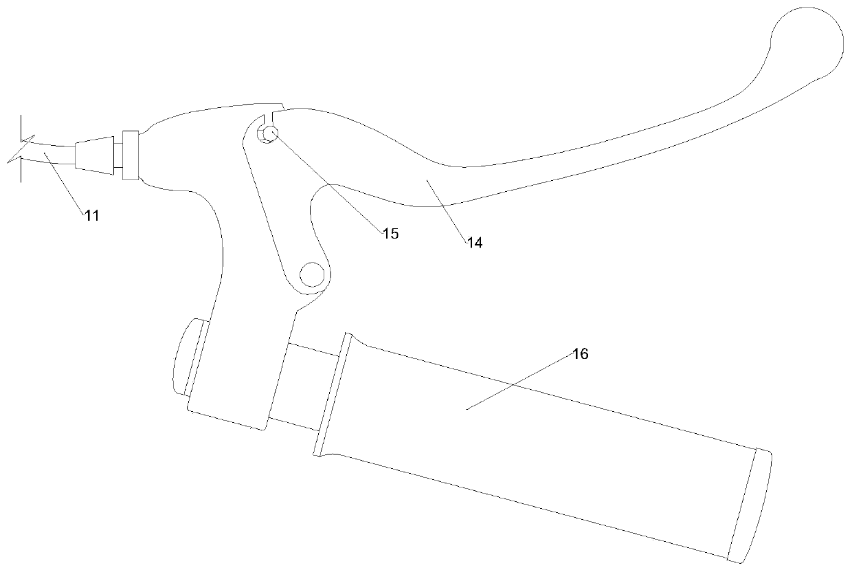
[0030] The brake line 7 is provided with a brake line cover 11, one end of the brake line cover 11 is connected to the brake handle, the other end of the brake line cover 11 is provided with a brake handle fine-tuning structure 12, and the brake handle fine-adjustment structure 12 is provided with a brake line 7 The line hole, the outer wall of the brake handle fine-tuning structure 12 is threadedly connected with the inner wall of the top opening of the shell 1; the brake handle fine-adjustment structure 12 is used to adjust the length of the pin pulling action.


PUM


Abstract

The invention provides a spring pin dismounting device. The spring pin dismounting device comprises a shell. An opening is formed in the lower end of the shell. A clamping position sleeve, a grabbingstructure and a connecting frame are arranged in the shell. A through hole is formed in the clamping position sleeve and comprises an upper section hole and a lower section hole. The grabbing structure is arranged in the lower section hole and comprises two hooking claws. Open holes are formed in the upper ends of the hooking claws, a connecting rod passes through the open holes of the two hookingclaws, and the two ends of the connecting rod are connected with the two installation ends of the bottom end of the connecting frame. One end of a brake cable is connected with the upper end of the connecting frame, and the other end of the brake cable passes out of an open hole formed in the top end of the shell and then is connected with a brake handle. A first spring and a second spring are arranged on the brake cable in a sleeving mode, the lower end of the first spring is connected with the connecting frame, and the lower end of the second spring is connected with the clamping position sleeve. According to the spring pin dismounting device, the remote control over the pin drawing operation is achieved by the brake cable, the adverse impact which is caused by the situation that the space structure is narrow and complex is avoided, the operation is easy and convenient, the pin drawing speed is high, the pin drawing success rate is high, and the spring pin dismounting device can beoperated by a single worker and is low in dependence on the experience and the technology of an operator.

Description

technical field [0001] The invention belongs to the technical field of spring pin extraction tools, in particular to a spring pin removal device. Background technique [0002] When pulling out the spring pin located in a narrow space, the operator is often unable to operate visually, and the operation is very inconvenient. At present, tools such as crowbars and pliers are generally used to perform the pin removal operation, but the operation is difficult, the success rate is low, it takes a long time, the efficiency is low, and the operator is prone to bumping and injury, and the experience and technical requirements of the operator are also relatively high. Contents of the invention [0003] In order to solve the above technical problems, the present invention provides a spring pin removal device, the removal device includes a shell with an open lower end, and the shell is provided with a clamping sleeve, a grabbing structure and a connecting frame; [0004] The clamping...

Claims


Application Information

Patent Timeline
Patent Type & Authority Applications(China)
IPC IPC(8): B25B27/02
CPCB25B27/02
Inventor 姜琳丁勃周滔
Owner LOTEEM BEIJING RAIL TRANSIT TECH CO LTD
Why Eureka
Try Eureka