Middle row seat mounting cross beam

A seat and crossbeam technology, which is applied in the field of middle row seat installation crossbeams, can solve the problems of poor torsional rigidity and side impact resistance, poor seat installation point stiffness, and long side impact force transmission path, etc., to improve the overall strength , Convenient installation and positioning, and the effect of reducing production costs

Inactive Publication Date: 2020-02-14
DONGFENG LIUZHOU MOTOR
View PDF6 Cites 0 Cited by
  • Summary
  • Abstract
  • Description
  • Claims
  • Application Information

AI Technical Summary

Problems solved by technology

[0003] The problem to be solved by the present invention is to provide a middle-row seat installation crossbeam, which can solve the problem that there are many types of parts used in the installation of the middle-row seats and the production cost is high; the side seat bracket is a cantilever structure, and the seat installation point rigidity Poor; the vehicle body suffers from side collision force transmission path is long, torsional rigidity and side collision performance are poor

Method used


Image

  • Middle row seat mounting cross beam
  • Middle row seat mounting cross beam
  • Middle row seat mounting cross beam

Examples


Embodiment Construction

[0020] The present invention will be described in further detail below in conjunction with accompanying drawing embodiment:

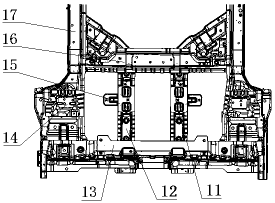
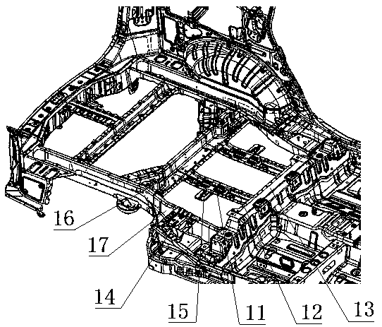
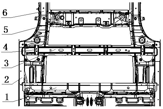
[0021] Such as image 3 The shown middle row seat installation beam includes a seat beam 3 located between the rear floor front beam 1 and the rear floor lower beam 5, and the two ends of the seat beam 3 respectively pass through the rear longitudinal beam 6 and the door sill beam 2 welding, four seat mounting brackets 4 are arranged at intervals on the seat beam 3 . The seat beam 3 has two side support plates 3-1 protruding upwards, and the two side support plates 3-1 are arranged oppositely along the length direction of the seat beam 3, and the side support plates 3-1 are provided at intervals for restricting the seat. The four positioning slots at the 4 positions of the chair mounting bracket, such as Figure 5 shown. The seat mounting bracket 4 has a mounting plate 4-1, and the mounting plate 4-1 is provided with two seat mounting holes, and the ...


PUM


Abstract

The invention discloses a middle row seat mounting cross beam, and relates to the technical field of automobile manufacturing. The middle row seat mounting cross beam comprises a seat cross beam located between a rear floor front cross beam and a rear floor lower cross beam. The two ends of the seat cross beam respectively penetrate through rear longitudinal beams to be fixedly connected with threshold beams. A plurality of seat mounting supports are arranged on the seat cross beam. Compared with the prior art, according to the middle row seat mounting cross beam, a seat in the middle and seats on two sides are mounted on the seat mounting supports, middle-row seats can be mounted through just two parts, few types of tools for production are required correspondingly, and the production cost is low. The seat mounting supports are arranged on the seat cross beam, a cantilever structure is eliminated, and the rigidity of a seat mounting point is improved. When a vehicle body is subjectedto side collision, through the rear floor front cross beam, the rear floor lower cross beam and the seat cross beam for force transmission, a side collision force transmission path is increased, sideimpact bearing performance is improved, and meanwhile, the torsional rigidity is effectively improved.

Description

technical field [0001] The invention relates to the technical field of automobile manufacturing, in particular to a crossbeam for installing middle-row seats. Background technique [0002] The installation structure of the middle seat in the traditional car is as follows: figure 1 As shown, two seat longitudinal beams 12 are welded between the rear floor front beam 13 and the rear floor lower beam 16, and the outer sides of the two seat longitudinal beams 12 respectively have side seat brackets 15 protruding outwards. The middle seat brackets 11 are respectively welded on the first seat longitudinal beam 12, and the side seat mounts 14 are respectively welded on the two rear longitudinal beams 17, and the seat in the middle is installed on the two middle seat brackets 11, The seats located on both sides are mounted on the side seat frame 15 and the side seat mount 14 . There are many types of parts used in the installation of the middle row of seats, and correspondingly ma...

Claims


Application Information

Patent Timeline
Patent Type & Authority Applications(China)
IPC IPC(8): B60N2/015B60N2/68B62D25/20
CPCB60N2/015B60N2/68B62D25/20
Inventor 唐竞林长波杨文静黄金荣陈祖兴
Owner DONGFENG LIUZHOU MOTOR
Why Eureka
Try Eureka