Sucker for flexible panel bonding and suction nozzle thereof

A suction cup, bonding technology, applied in the direction of conveyor objects, transportation and packaging, can solve the problems affecting the cleanliness and production yield of flexible panel production, production yield, fine particle pollution, etc., to improve cleanliness and production yield. Effect

Pending Publication Date: 2020-02-14
TDG MACHINERY TECH
0 Cites 0 Cited by

AI-Extracted Technical Summary

Problems solved by technology

Therefore, when the suction nozzle is working, the telescopic action will cause friction between the telescopic mechanism and the suction nozzle base, and the wear of mechanical parts will ...

Method used

On the basis of above-mentioned embodiment, moving shaft 2 can be provided with the installation step of installing cushioning part for the part that is socketed with base body 1, and buffering part is socketed on moving shaft 2, and one end of buffering part and mounting step In contact, the other end of the buffer is in contact with the end surface of the inner hole of the base body 1 . Therefore, the buffer member can play a buffering role when the moving shaft 2 moves up and down along the length direction of the base body 1 .
Preferably, sealing ring 6 can be provided between connecting section and suction nozzle mounting hole, thereby avo...

Abstract

The invention discloses a suction nozzle, which comprises a base body used for connecting with a sucker and communicating with a vacuum device, a suction head used for contacting with an object to besucked, a telescopic mechanism for driving the suction head to move up and down in a length direction of the base body and a buffer piece, wherein the suction head is arranged at one end of the telescopic mechanism away from the base body, and the buffer piece is arranged between the base body and the telescopic mechanism; the base body is sleeved in the suction nozzle mounting hole of the sucker,and the telescopic mechanism is sleeved in the inner hole of the base body. The base body is integrally sleeved in the suction nozzle mounting hole of the sucker, so the base body and the componentsinstalled in the inner hole of the base body are located in the vacuum circuit of the sucker. When the vacuum device works and manufactures a negative pressure environment in the sucker, fine particles produced by the friction of the base body and the telescopic mechanism can be automatically and continuously sucked away by the vacuum device, so the cleanliness and production yield of the flexiblepanel during production and transportation are improved effectively. In addition, the invention further discloses a sucker for the flexible panel bonding comprising the suction nozzle.

Application Domain

Conveyor parts

Technology Topic

EngineeringStructural engineering +1

Image

  • Sucker for flexible panel bonding and suction nozzle thereof
  • Sucker for flexible panel bonding and suction nozzle thereof
  • Sucker for flexible panel bonding and suction nozzle thereof

Examples

  • Experimental program(1)

Example Embodiment

[0028] The technical solutions in the embodiments of the present invention will be clearly and completely described below in conjunction with the accompanying drawings in the embodiments of the present invention. Obviously, the described embodiments are only a part of the embodiments of the present invention, rather than all the embodiments. Based on the embodiments of the present invention, all other embodiments obtained by those of ordinary skill in the art without creative work shall fall within the protection scope of the present invention.
[0029] The core of the present invention is to provide a suction nozzle whose telescopic component is located in the vacuum circuit of the suction cup, and fine particles generated by the telescopic movement can be automatically and continuously sucked away by the vacuum device, which improves the cleanliness and production yield of flexible panel production and transportation.
[0030] The invention also provides a suction cup for bonding a flexible panel including the suction nozzle.
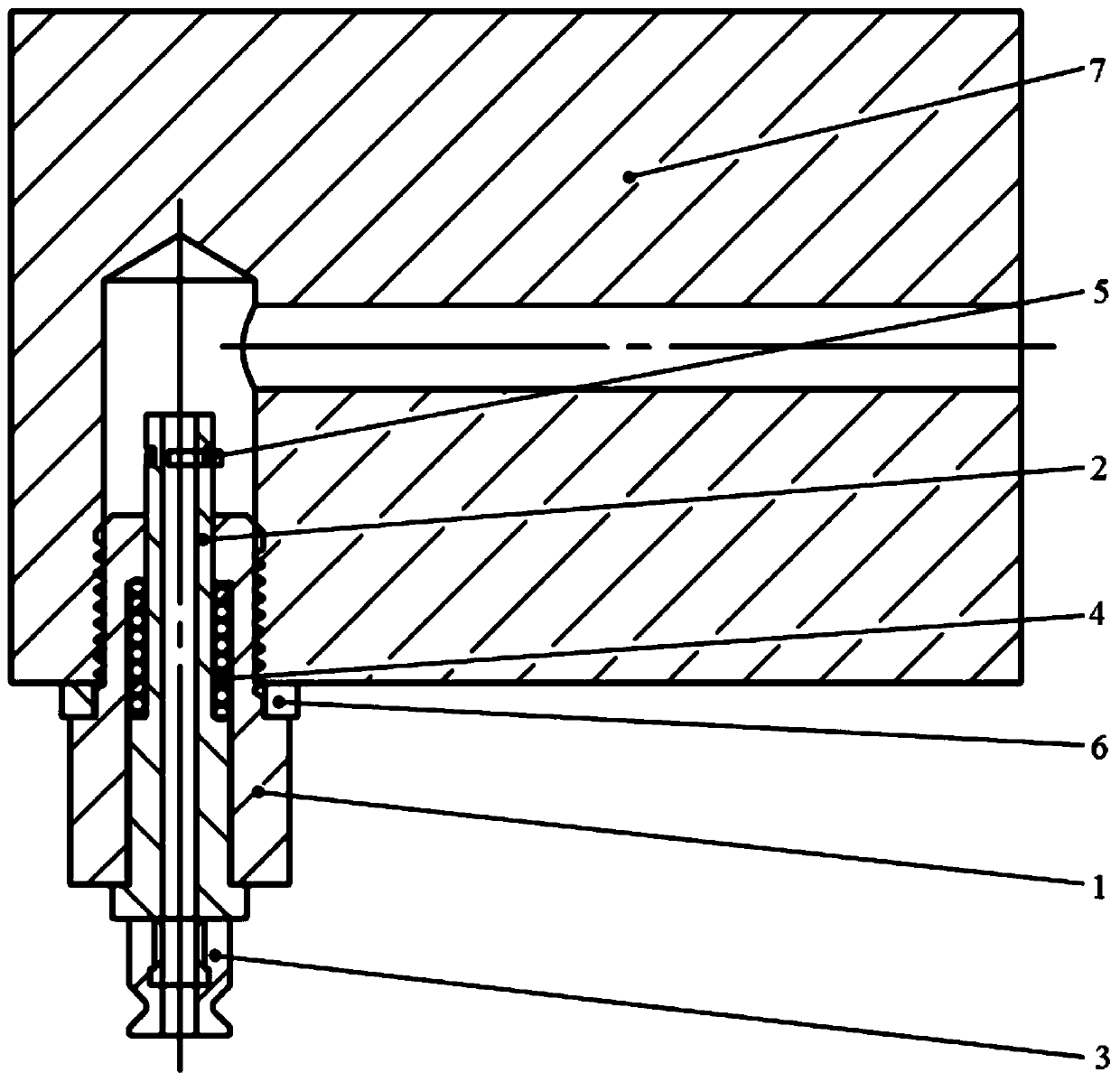
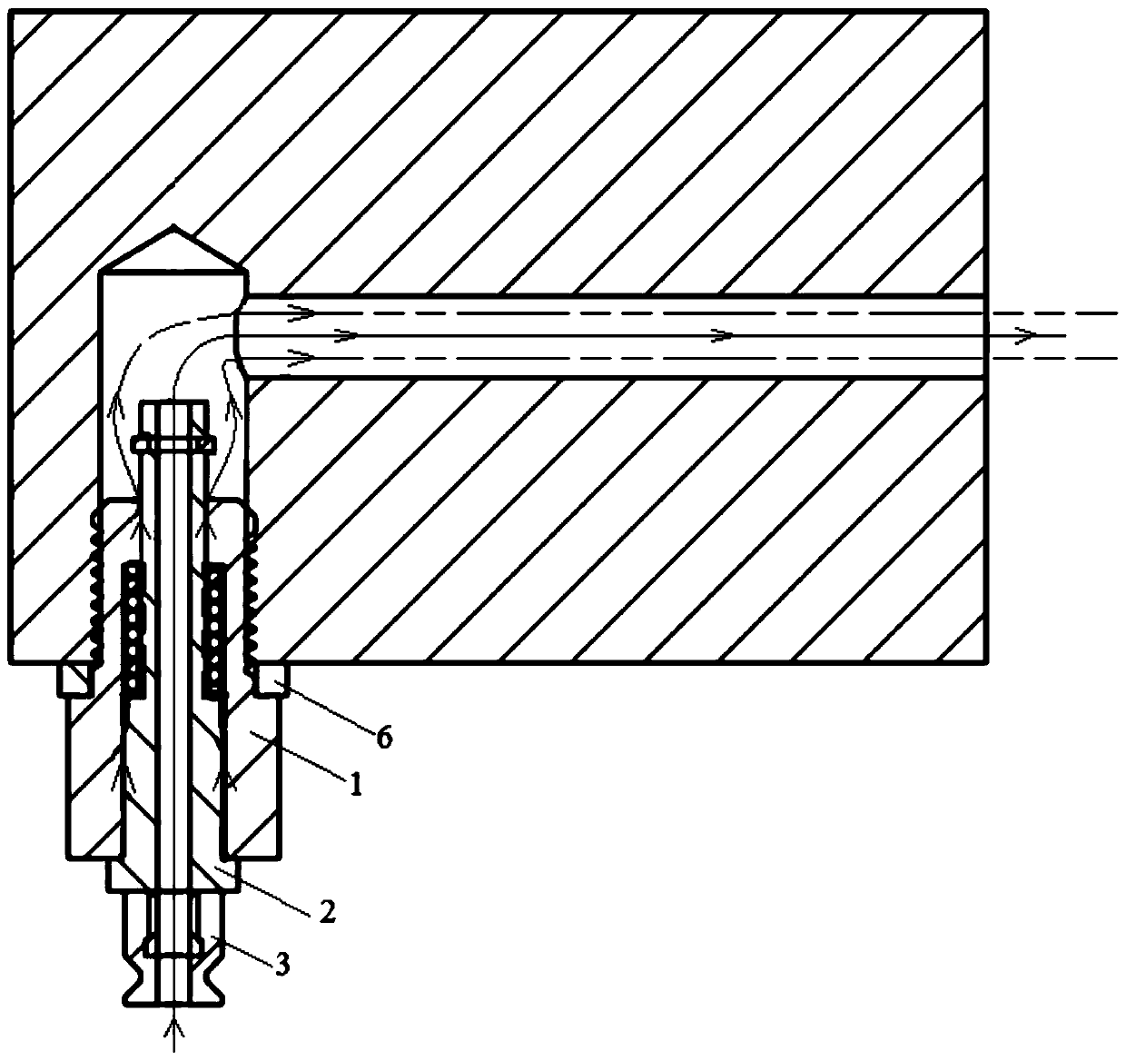
[0031] Please refer to Figure 1-Figure 4 , figure 1 Is a schematic diagram of the structure of the suction nozzle in the prior art; figure 2 Is a schematic diagram of the structure of the vacuum circuit of the suction nozzle in the prior art; image 3 It is a schematic structural diagram of a specific embodiment of the suction nozzle provided by the present invention; Figure 4 for image 3 Schematic diagram of the vacuum circuit of the middle nozzle.
[0032] The suction nozzle provided by the present invention includes a base 1 for connecting with a suction cup to communicate with a vacuum device, a suction head 3 for contacting an object to be sucked, and a telescopic mechanism that drives the suction head 3 to move up and down along the length of the base 1 And a buffering member, the suction head 3 is arranged at the end of the telescopic mechanism away from the base 1, and the buffering member is provided between the base 1 and the telescopic mechanism; the base 1 is sleeved in the suction nozzle installation hole of the suction cup, and the telescopic mechanism is sleeved on the base 1 Inner hole.
[0033] Please refer to figure 1 , The base body 1 is sleeved in the nozzle mounting hole on the nozzle mounting plate 7, and the nozzle mounting hole is connected to the vacuum device. For the structure of the nozzle mounting hole, please refer to the prior art of the suction cup structure, which will not be repeated here.
[0034] Preferably, the base body 1 may include a threaded section for connecting with the nozzle mounting hole and a connecting section connected with the threaded section, and the diameter of the threaded section is smaller than the diameter of the connecting section. The threaded section is sleeved in the nozzle mounting hole, and the connecting section plays a role in positioning. When installing, screw the base 1 until the connecting section is in contact with the nozzle mounting plate 7.
[0035] The length of the connecting section is determined according to factors such as the stroke of the telescopic mechanism, the connection strength of the suction nozzle and the suction cup, and the diameter of the connecting section is determined according to factors such as the diameter of the threaded section.
[0036] Preferably, a sealing ring 6 may be provided between the connecting section and the nozzle mounting hole, so as to avoid air intake from the gap between the connecting end and the nozzle mounting plate 7 during the vacuum extraction process, thereby increasing the load of the vacuum device, and Affect the effect of vacuum extraction, and then affect the suction capacity of the suction cup.
[0037] Please refer to Figure 4 , The direction of the arrow in the figure is the direction of air pressure, the solid line represents the main circuit in the vacuum circuit of the suction cup for achieving the negative pressure adsorption function, and the dotted line is the direction of air flow at the fine particles. When the vacuum device is working, since the base body 1 is completely sleeved in the nozzle mounting hole of the suction cup, the contact surface of the telescopic mechanism and the base body 1 is also in the vacuum circuit of the suction cup, so fine particles will be continuously and automatically sucked away by the vacuum device.
[0038] In this embodiment, the base 1 is integrally sleeved in the suction nozzle mounting hole of the suction cup. Since the nozzle mounting hole is connected to the vacuum device, the base 1 and the telescopic mechanism installed in the inner hole of the base 1 are both located in the vacuum circuit of the suction cup When the vacuum device is working to create the negative pressure environment in the suction head 3, the fine particles generated by the friction between the telescopic mechanism and the base 1 can be automatically and continuously sucked away by the vacuum device. Compared with the prior art, the inner hole of the base 1 passes through the trachea. The joint 02 is connected with the air pipe 01, and the airflow only flows through the inner hole of the telescopic mechanism, which cleverly utilizes the vacuum negative pressure of the suction nozzle, which effectively improves the cleanliness and production yield of the flexible panel production and transportation.
[0039] On the basis of the above embodiment, the structure of the telescopic mechanism is limited. The telescopic mechanism may include a moving shaft 2 sleeved in the base 1, the moving shaft 2 penetrates the inner hole of the base 1, and the moving shaft 2 can be along the length of the base 1. Move up and down in the direction; both ends of the moving shaft 2 are provided with a limit structure for limiting the range of movement of the moving shaft 2.
[0040] The suction head 3 is connected to the end surface of the moving shaft 2, and the inner hole of the moving shaft 2 communicates with the inner hole of the suction head 3, so that the air between the suction head 3 and the object to be sucked can be drawn out through a vacuum device to form a negative pressure.
[0041] The size of the inner hole of the moving shaft 2 and the size of the inner hole of the suction head 3 may be the same or different. Preferably, the inner hole of the moving shaft 2 and the inner hole of the suction head 3 can be set to the same size to avoid air flow The cross-sectional area of ​​the channel changes abruptly, increasing air resistance, thereby increasing the load of the vacuum device.
[0042] The specific dimensions of the inner hole of the moving shaft 2 and the inner diameter of the suction head are determined according to actual production needs.
[0043] Preferably, the upper end of the moving shaft 2 may be provided with a clamping slot for installing the circlip 5, and the circlip 5 restricts the farthest downward movement of the moving shaft 2.
[0044] Of course, the circlip 5 can also be replaced with a mechanism with similar functions, such as a limit step, a limit block, and the like.
[0045] Preferably, a limiting step may be provided at the lower end of the moving shaft 2, the diameter of the limiting step is larger than the diameter of the inner hole of the base body 1 to limit the farthest upward movement of the moving shaft 2.
[0046] Take the end surface connecting the moving shaft 2 and the suction head 3 as the fixed end, and the other end as the free end. The distance between the card slot and the free end of the moving shaft 2 and the distance between the limit step and the fixed end of the moving shaft 2 are carried out according to actual production needs. determine.
[0047] On the basis of the above embodiment, the part of the moving shaft 2 for socketing with the base body 1 may be provided with an installation step for installing a buffer, the buffer is sleeved on the moving shaft 2, and one end of the buffer is in contact with the installation step to buffer The other end of the piece is in contact with the end surface of the inner hole of the base 1. Therefore, the buffer can play a buffering role when the moving shaft 2 moves up and down along the length direction of the base body 1.
[0048] Preferably, the buffer member may be a buffer spring 4.
[0049] In addition to the above-mentioned suction nozzle, the present invention also provides a suction cup for flexible panel bonding including the suction nozzle disclosed in the above embodiment. The suction cup includes a nozzle mounting plate 7 and a plurality of suction nozzles. The nozzle mounting plate 7 is provided with a plurality of suction nozzles. A nozzle mounting hole for mounting a nozzle, where the nozzle is the nozzle disclosed in the above embodiment.
[0050] The number and layout of the nozzle mounting holes on the nozzle mounting plate 7 are determined according to actual production needs.
[0051] Please refer to figure 1 with figure 2 Preferably, the suction nozzle installation hole may be L-shaped, and includes a suction nozzle installation section connected with the suction nozzle and a vacuum connection section connected with the vacuum device.
[0052] The various embodiments in this specification are described in a progressive manner. Each embodiment focuses on the differences from other embodiments, and the same or similar parts between the various embodiments can be referred to each other.
[0053] The suction cup and the suction nozzle for bonding of the flexible panel provided by the present invention are described in detail above. Specific examples are used in this article to illustrate the principle and implementation of the present invention. The description of the above examples is only used to help understand the method and core idea of ​​the present invention. It should be pointed out that for those of ordinary skill in the art, without departing from the principle of the present invention, several improvements and modifications can be made to the present invention, and these improvements and modifications also fall within the protection scope of the claims of the present invention.

PUM

no PUM

Description & Claims & Application Information

We can also present the details of the Description, Claims and Application information to help users get a comprehensive understanding of the technical details of the patent, such as background art, summary of invention, brief description of drawings, description of embodiments, and other original content. On the other hand, users can also determine the specific scope of protection of the technology through the list of claims; as well as understand the changes in the life cycle of the technology with the presentation of the patent timeline. Login to view more.
Why Eureka
Try Eureka