Plastic pump impeller and plastic pump impeller forming die

A technology for forming molds and plastic pumps, which is applied in the direction of pumps, pump components, non-variable pumps, etc., can solve the problems of easy deformation, large impeller diameter, and reduced flow rate, so that it is no longer easy to deform, increase strength, reduce The effect of small distance

Inactive Publication Date: 2020-02-14
安徽龙泉泵阀制造有限公司
View PDF4 Cites 0 Cited by
  • Summary
  • Abstract
  • Description
  • Claims
  • Application Information

AI Technical Summary

Problems solved by technology

Therefore, the blades of the impeller of the plastic pump cannot be excessively extended to the inlet, and cannot be distorted. Therefore, the flow area of ​​the impeller of the plastic pump is much smaller than that of the impeller of the metal pump, and the width of the impeller outlet is fixed, so the area of ​​the outlet and inlet of the impeller of the plastic pump is fixed. The diffusion ratio is much larger than that of metal pumps, especially when used with small flow and high head, the diameter of the impeller is large, and the diffusion ratio of the outlet and inlet areas of the impeller is larger, resulting in a sudden drop in the pressure at the outlet between the two blades of the impeller due to area diffusion
The liquid always flows from high pressure to low pressure, and the position near the blade at the outlet is a high pressure area, then the liquid will flow from high pressure to low pressure area, and the liquid cannot be centrifugally thrown out by the impeller in time, which affects the flow rate, lift and efficiency
Since the front and rear cover plates of the impeller are also high-pressure areas, and the front and rear cover plates of the plastic pump impeller are plastic, which are easily deformed under long-term pressure. Concave inwards to block the outlet area, and finally the flow rate decreases or even stops

Method used


Image

  • Plastic pump impeller and plastic pump impeller forming die
  • Plastic pump impeller and plastic pump impeller forming die
  • Plastic pump impeller and plastic pump impeller forming die

Examples


Embodiment Construction

[0022] The following will clearly and completely describe the technical solutions in the embodiments of the present invention with reference to the accompanying drawings in the embodiments of the present invention. Obviously, the described embodiments are only some, not all, embodiments of the present invention. Based on the embodiments of the present invention, all other embodiments obtained by persons of ordinary skill in the art without making creative efforts belong to the protection scope of the present invention.

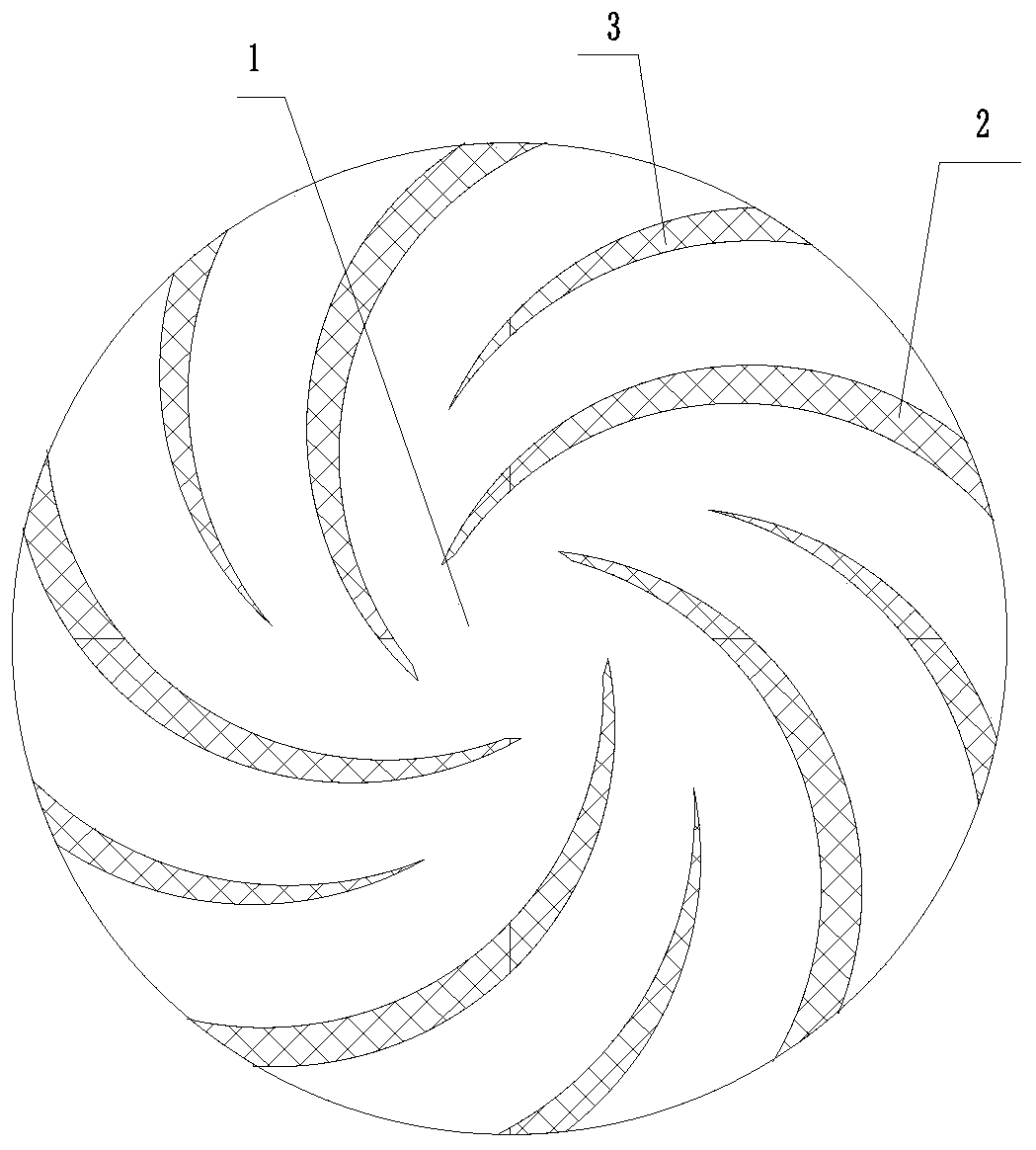
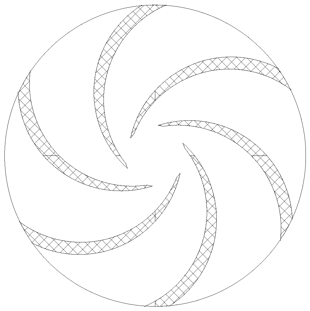
[0023] figure 1 A kind of plastic pump impeller provided for the present invention, in the middle of two blades 2 of impeller 1 (existing impeller, such as figure 2 ) (in the middle of the position of the appeal low-pressure area), add a section of pressurized vane 3 and extend to the outlet.

[0024] The thickness of the pressurized blade 3 is designed according to the original blade 2 and according to the flow direction of the liquid.

[0025] When the li...


PUM


Abstract

The invention discloses a plastic pump impeller and a plastic pump impeller forming die. A pressurization blade is added to the space between two blades of a conventional impeller of a plastic pump and extends to an outlet. The thickness of the pressurization blades is designed according to an original blade in the liquid flowing direction. When flowing to the initial positions of the pressurization blades, the liquid is pressurized again until being forced to get away from the impeller at high speed. The staying time of the liquid between the blades is shortened, and pressure is uniformly applied to the liquid. Thus, the plastic pump impeller can improve the flow, the lift and efficiency of the plastic pump. The blades are added to the outlet of the plastic pump impeller. The distance between every two blades is reduced. The strength of front and rear cover plates of the impeller is improved. The plastic impeller is not likely to deform any longer.

Description

technical field [0001] The invention relates to the technical field of pump valves, in particular to a plastic pump impeller and a molding die thereof. Background technique [0002] The plastic pump impeller needs to be demolded from the impeller outlet position due to the mold drawing block (plug piece) between the impeller blades during molding, and the outlet width determines the thickness of the plug piece. Therefore, the blades of the impeller of the plastic pump cannot be excessively extended to the inlet, and cannot be twisted, so the flow area of ​​the impeller of the plastic pump is much smaller than that of the impeller of the metal pump, and the width of the impeller outlet is fixed, so the area of ​​the outlet and inlet of the impeller of the plastic pump is fixed. The diffusion ratio is much larger than that of metal pumps, especially when used with small flow and high head, the diameter of the impeller is large, and the diffusion ratio of the outlet and inlet a...

Claims


Application Information

Patent Timeline
Patent Type & Authority Applications(China)
IPC IPC(8): F04D29/22F04D29/24F04D29/02B29C43/36
CPCB29C43/36F04D29/026F04D29/2294F04D29/242
Inventor 凤金泉凤元树耿辉吴玲萍凤笑笑
Owner 安徽龙泉泵阀制造有限公司
Why Eureka
Try Eureka