Rotating shaft mechanism for notebook computer

A notebook computer and shaft technology, applied in the direction of pivots, mechanical equipment, shafts, and bearings, can solve the problems of complex production and installation, adjustment, and high cost, and achieve the effects of simple structure installation, anti-distortion, and low cost

Inactive Publication Date: 2020-02-14
KUNSHAN KERSEN SCI & TECH
View PDF6 Cites 0 Cited by
  • Summary
  • Abstract
  • Description
  • Claims
  • Application Information

AI Technical Summary

Problems solved by technology

However, the above-mentioned structures can only realize a certain angle of opening and closing between the notebook screen and the base, and cannot satisfy the 360-degree rotating and positioning function required in the two-in-one combination of a tablet and a notebook computer.
[0003] In the prior art, in order to achieve 360-degree rotation, the gear structure is mostly used. However, the center distance of the two shafts of the gear structure is limited and cannot be freely adjusted according to the size of the object to be used. It is necessary to determine the center distance through calculation of gear matching, production and installation. Complicated and requires many parts and high cost

Method used


Image

  • Rotating shaft mechanism for notebook computer
  • Rotating shaft mechanism for notebook computer
  • Rotating shaft mechanism for notebook computer

Examples


Embodiment 1

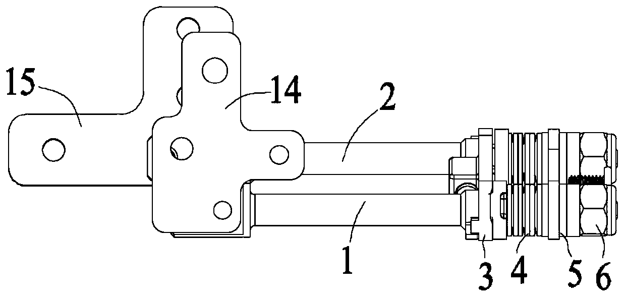
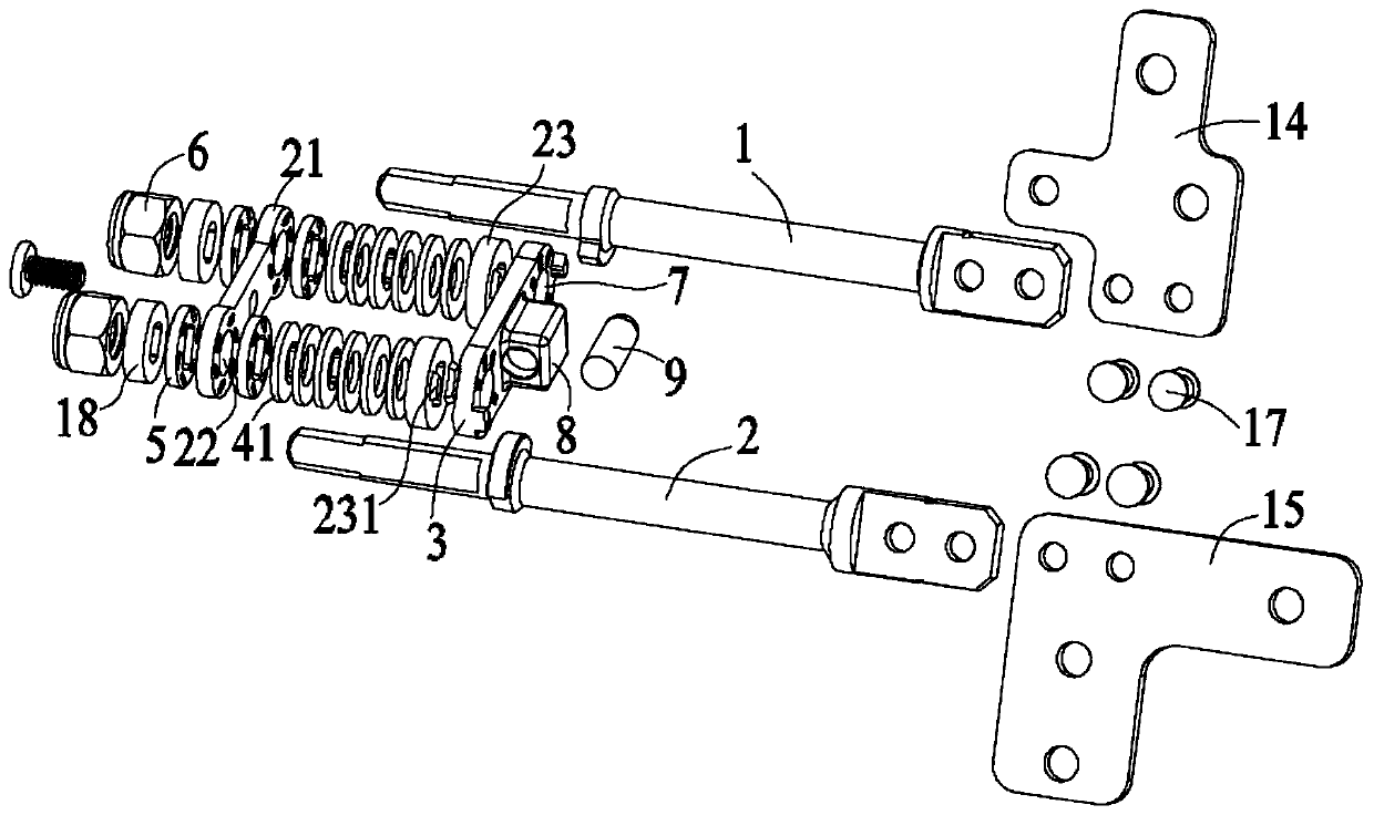
[0030] Embodiment 1: A shaft mechanism for a notebook computer, including a first shaft 1, a second shaft 2, a support plate 3 connecting the first shaft 1 and the second shaft 2, an elastic assembly 4, several friction plates 5 and stoppers Block 6, the support plate 3, the elastic component 4 and the friction plate 5 are sequentially set on the first rotating shaft 1 and the second rotating shaft 2 respectively, and are squeezed and fixed by the stopper 6;

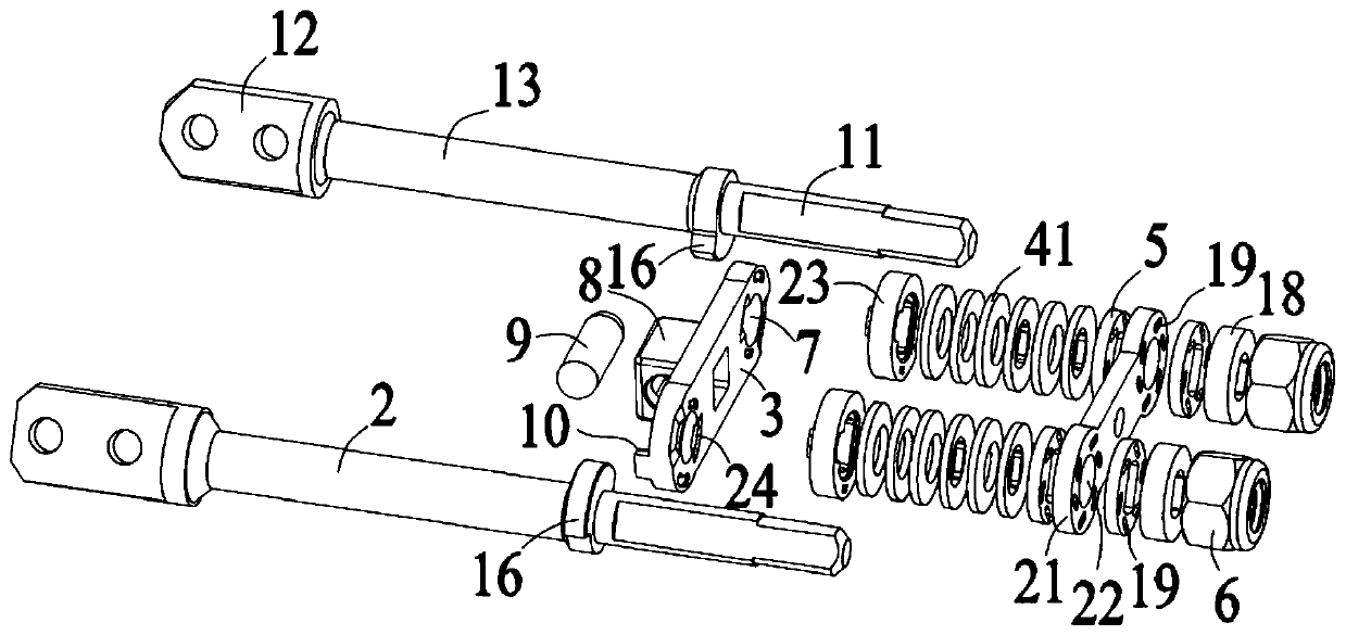
[0031] Both the first rotating shaft 1 and the second rotating shaft 2 include a power storage part 11 at one end, a connection part 12 at the other end, and a polished rod part 13 between the power storage part 11 and the connection part 12. The power storage part The support plate 3, the elastic assembly 4 and the friction plate 5 are sequentially set on the 11, a first connecting plate 14 is connected to the connecting portion 12 of the first rotating shaft 1, and a first connecting plate 14 is connected to the connect...

Embodiment 2

[0038] Embodiment 2: A shaft mechanism for a notebook computer, including a first shaft 1, a second shaft 2, a support plate 3 connecting the first shaft 1 and the second shaft 2, an elastic assembly 4, several friction plates 5 and stoppers Block 6, the support plate 3, the elastic component 4 and the friction plate 5 are sequentially set on the first rotating shaft 1 and the second rotating shaft 2 respectively, and are squeezed and fixed by the stopper 6;

[0039] Both the first rotating shaft 1 and the second rotating shaft 2 include a power storage part 11 at one end, a connection part 12 at the other end, and a polished rod part 13 between the power storage part 11 and the connection part 12. The power storage part The support plate 3, the elastic assembly 4 and the friction plate 5 are sequentially set on the 11, a first connecting plate 14 is connected to the connecting portion 12 of the first rotating shaft 1, and a first connecting plate 14 is connected to the connect...


PUM


Abstract

The invention discloses a rotating shaft mechanism for a notebook computer. The rotating shaft mechanism comprises a first rotating shaft, a second rotating shaft, a supporting plate connecting the first rotating shaft with the second rotating shaft, an elastic assembly, a plurality of friction sheets and stop blocks, wherein the supporting plate, and the elastic assembly and the friction sheets sequentially sleeve the first rotating shaft, the second rotating shaft and are extruded and fixed through the stop blocks; a second supporting plate connecting the first rotating shaft with the secondrotating shaft is arranged between the stop blocks and the elastic assembly, wherein two second through holes allowing force storing portions of the first rotating shaft and the second rotating shaftto pass through are correspondingly formed in the second supporting plate, and the plurality of friction sheets are located on the two sides of the second supporting plate correspondingly; a cam is arranged between the supporting plate and the elastic assembly, and a groove matched with a convex block of the cam is formed in the surface, opposite to a sliding block base, of the supporting plate.According to the rotating shaft mechanism for the notebook computer, 360-degree rotation positioning can be realized, adjustment of center distances for the rotating shafts can be achieved only by adjusting the length of a sliding top block, and therefore the rotating shaft mechanism is suitable for notebook computers with different specifications and sizes.

Description

technical field [0001] The invention relates to a rotating shaft mechanism for a notebook computer, which belongs to the technical field of notebook computers. Background technique [0002] The rotating shaft is a connecting element that can provide mutual rotation. It is mainly used between the rotating parts and its base. At present, it is widely used in various digital products and electronic equipment, such as notebook computers. The rotation of the notebook computer can be achieved through the rotation of the rotating shaft. The opening and closing function between the main body and the display screen. At present, the commonly used rotating shaft is a single-axis core, and the opening and closing and automatic closing functions of the notebook computer are realized by positioning the cam and the concave wheel sleeved on the single-axis core. There is also a dual-axis core to realize the opening and closing of the laptop and the angle relative to the human body. Howeve...

Claims


Application Information

Patent Timeline
Patent Type & Authority Applications(China)
IPC IPC(8): F16C11/04F16C11/10G06F1/16
CPCF16C11/045F16C11/103G06F1/1681
Inventor 董小慧万鹏程陳威仲
Owner KUNSHAN KERSEN SCI & TECH
Why Eureka
Try Eureka