Helicopter rotor damper displacement measuring device

A technology of helicopter rotor and damper, applied in the direction of mechanical measuring device, measuring device, adopting mechanical device, etc.

Active Publication Date: 2020-02-14
CHINA HELICOPTER RES & DEV INST
View PDF6 Cites 0 Cited by
  • Summary
  • Abstract
  • Description
  • Claims
  • Application Information

AI Technical Summary

Problems solved by technology

For this kind of damper displacement measurement method, laser displacement sensors and baffles are often used to measure the relative displacement of the fixed points at both ends of the damper. This method is not suitable for the displacement measurement of disc dampers.

Method used


Image

  • Helicopter rotor damper displacement measuring device
  • Helicopter rotor damper displacement measuring device
  • Helicopter rotor damper displacement measuring device

Examples


Embodiment Construction

[0024] The following will clearly and completely describe the technical solutions in the embodiments of the present invention in conjunction with the accompanying drawings in the embodiments of the present invention. Obviously, the described embodiments are only some of the embodiments of the present invention, not all of them. Based on the embodiments of the present invention, all other embodiments obtained by persons of ordinary skill in the art without making creative efforts belong to the protection scope of the present invention.

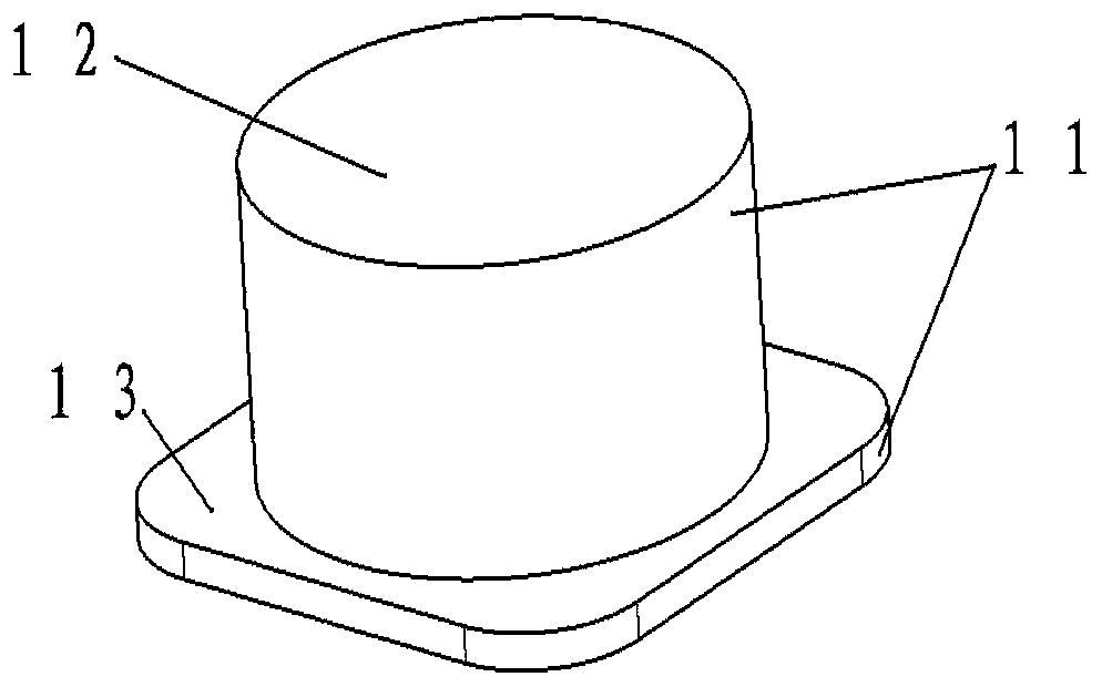
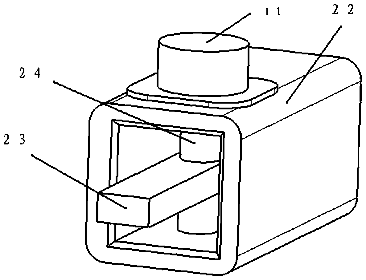
[0025] A method for measuring the displacement of a helicopter rotor damper, comprising a push rod type displacement sensor and an installation tool.

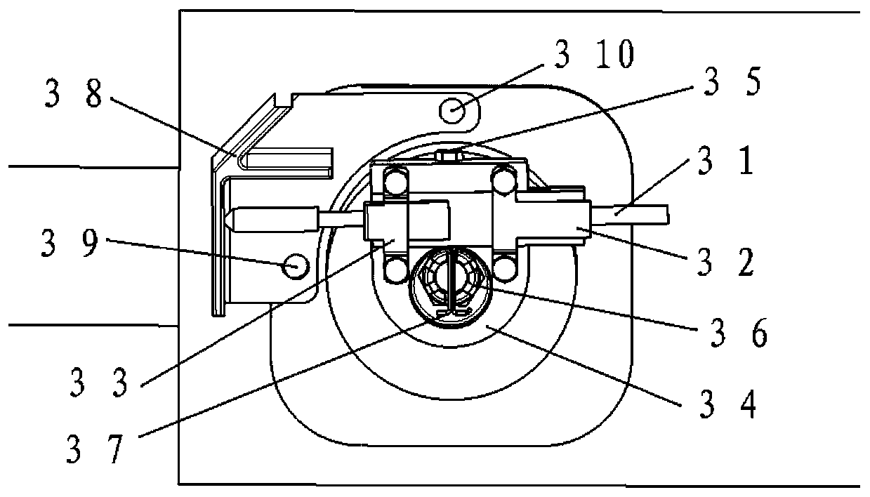
[0026] The first T-shaped cassette 32 and the second T-shaped cassette 33 fix the displacement sensor 31 on the mounting bracket 34. The bottoms of the first T-shaped cassette 32 and the second T-shaped cassette 33 are bent and bonded to the displacement sensor 31. A groove is provided, and the ...


PUM


Abstract

The invention belongs to the field of helicopter comprehensive tests, and relates to a helicopter rotor damper displacement measuring device. The device comprises a mounting bracket, a first clampingbelt, a second clamping belt, a displacement sensor and an ejector rod baffle, wherein the mounting bracket is arranged on a damper; the ejector rod baffle is arranged on a rotor; the displacement sensor is fixed on the bracket through the first clamping belt and the second clamping belt; the first clamping belt and the second clamping belt are fixed at the two ends of the displacement sensor respectively; and the ejector rod baffle is perpendicular to the measuring end of the displacement sensor. The device can measure the displacement of the disc type damper and the helicopter rotor.

Description

technical field [0001] The invention belongs to the field of helicopter comprehensive tests and relates to a displacement measuring device for a helicopter rotor damper. Background technique [0002] The disc type viscoelastic damper 11 is a special structural damper for damping the shimmy motion of the blade. Among them, the damper upper cover plate 12 is fixed on the root of the flexible beam 23 of the support arm through the support rod, and the damper lower cover plate 13 is fixed on the support arm sleeve 22 through bolts. When the propeller drives the support arm to move in the swing direction, due to The sleeve 22 is rigid in the shimmy direction, and will drive the lower cover plate 13 of the damper, so that the upper cover plate 12 and the lower cover plate 13 of the damper generate relative motion along the shimmy direction of the support arm. Measuring the relative motion displacement when the helicopter rotor is running is of great significance to the safety mon...

Claims


Application Information

Patent Timeline
Patent Type & Authority Applications(China)
IPC IPC(8): G01B21/02B64F5/60
CPCB64F5/60G01B5/0004G01B21/02
Inventor 章猛杨月章华彭苏雁雷少保秦强张文静
Owner CHINA HELICOPTER RES & DEV INST
Why Eureka
Try Eureka