A suction force device for automatic testing of electromagnetic brakes in complex application environments

A technology of electromagnetic brake and application environment, which is applied in the direction of measuring devices, testing of mechanical components, testing of machine/structural components, etc. It can solve the problems of limited testing environment, smaller braking torque of electromagnetic brakes, and overall performance of electromechanical actuators. To achieve the effect of broadening the test environment, improving accuracy and precision, and measuring precision

Active Publication Date: 2021-10-01
BEIJING RES INST OF PRECISE MECHATRONICS CONTROLS
View PDF7 Cites 0 Cited by
  • Summary
  • Abstract
  • Description
  • Claims
  • Application Information

AI Technical Summary

Problems solved by technology

[0004] Existing test devices are generally operated manually, and manual operation results in limited test environments for existing test devices
Due to the limitation of the application environment of the electromechanical actuator, the electromagnetic brake is subject to unknown restrictions, which makes the braking torque of the electromagnetic brake smaller, which will inevitably reduce the performance of the electromechanical actuator. Therefore, how to operate in a complex environment and in a shorter time Realizing the testing of electromagnetic brakes in complex application environments and solving the key technical application requirements of electromechanical actuators is one of the technical difficulties that need to be overcome within a short period of time.

Method used


Image

  • A suction force device for automatic testing of electromagnetic brakes in complex application environments
  • A suction force device for automatic testing of electromagnetic brakes in complex application environments
  • A suction force device for automatic testing of electromagnetic brakes in complex application environments

Examples


Embodiment Construction

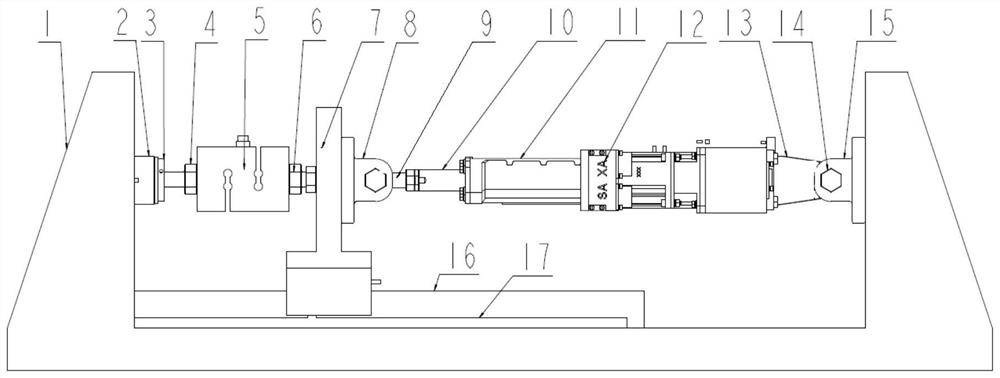
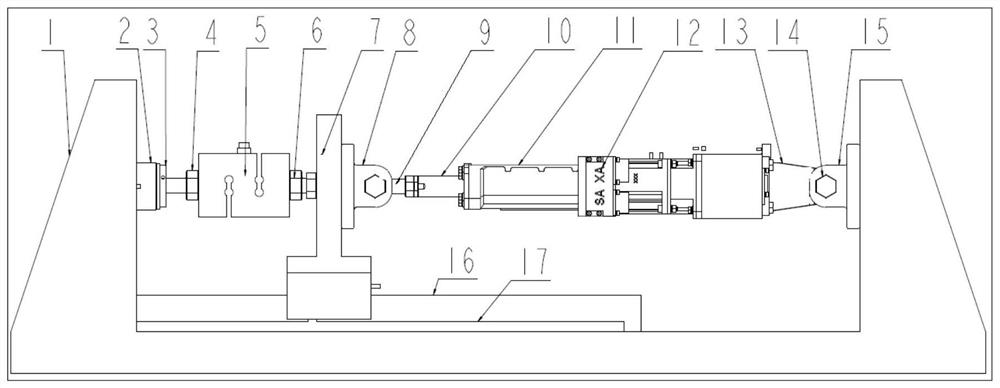
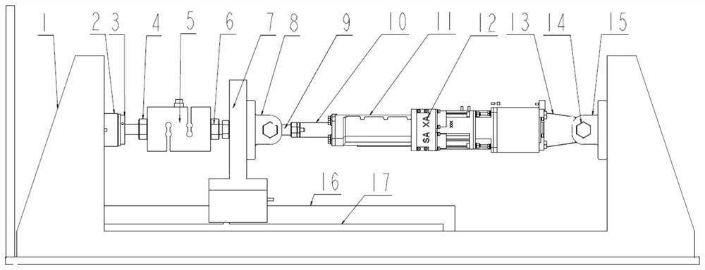
[0033] The present invention proposes a suction force device for automatically testing electromagnetic brakes in a complex application environment, including a base 1, a brake connecting shaft 4, a tension pressure sensor 5, a tension pressure sensor connection shaft 6, a sliding plate 7, and front lugs Seat 8, electromechanical actuator, rear lug support 15, guide rail 16, grating ruler 17.

[0034] The base 1 has a U-shaped structure, and the electromagnetic brake stator 2 is fixed at the "|"-shaped structure on one side of the base 1. The electromagnetic brake mover 3 is connected to the pull-pressure sensor 5 through the brake connection shaft 4, and the pull-pressure sensor 5 passes the pressure The sensor connecting shaft 6 is fixed on one side of the sliding plate 7, the other side of the sliding plate 7 is installed with the front lug support 8, and the rear lug support 15 is installed at the “|” type structure on the other side of the base 1, the electromechanical The...


PUM

PropertyMeasurementUnit
verticalityaaaaaaaaaa

Abstract

The invention discloses a suction force device for automatically testing an electromagnetic brake in a complex application environment. The base is a U-shaped structure, the stator of the electromagnetic brake is fixed on one side of the base, and the mover of the electromagnetic brake is connected to a tension and pressure sensor through a brake shaft. Connection, the tension pressure sensor is fixed on one side of the slide plate through the pressure sensor connection shaft, the front lug support is installed on the other side of the slide plate, the rear support lug support is installed on the other side of the base, and the electromechanical actuator passes through the The actuator connecting bolt is fixed between the front lug support and the rear lug support. The guide rail and the grating ruler are installed on the bottom surface of the base, the sliding plate is vertically installed on the guide rail, the sliding plate can slide back and forth along the guide rail, and the grating ruler is used to measure the displacement of the sliding plate on the guide rail. The invention can automatically test the attraction force of the electromagnetic brake, and compared with the manually operated test device, the test environment is obviously widened.

Description

technical field [0001] The invention relates to a suction force device for automatically testing electromagnetic brakes in complex application environments, which belongs to electromechanical servo technology and is suitable for brake testing of redundant electromechanical actuators. Background technique [0002] The electromechanical actuator has its very outstanding advantages, and its application is also expanding rapidly. Therefore, new requirements are put forward for the electromechanical actuator to achieve more reliable performance. In order to ensure safe and reliable performance, it is necessary to realize power redundancy. Therefore, the redundant power Braking is particularly important, and the reliability of braking force is the most important. [0003] The motor of the electromechanical actuator is the power, and the redundancy of power can ensure that the performance of the actuator is safer and more reliable. In comparison, the differential speed redundancy s...

Claims


Application Information

Patent Timeline
Patent Type & Authority Patents(China)
IPC IPC(8): G01M13/00G01L5/28
CPCG01L5/28G01L5/284G01M13/00
Inventor 侯占林黄玉平王春明肖翀崔佩娟
Owner BEIJING RES INST OF PRECISE MECHATRONICS CONTROLS
Why Eureka
Try Eureka