Supercharge Your Innovation With Domain-Expert AI Agents!

Automatically control teaching demonstration device

A demonstration device and drive disk technology, applied in projection devices, optics, educational appliances, etc., can solve the problems of not being able to meet the viewing requirements of different teachers, the size of the screen cloth can not be adjusted, the size of the projection area can be adjusted, etc., to achieve easy display Angle, easy to adjust, easy to use effect

Inactive Publication Date: 2020-02-14
厦门软件职业技术学院
View PDF7 Cites 1 Cited by
  • Summary
  • Abstract
  • Description
  • Claims
  • Application Information

AI Technical Summary

Problems solved by technology

[0003] However, the size and area of ​​the screen cloth of the multimedia teaching projection in the prior art cannot be adjusted, so only certain information can be fixedly projected each time, and the projected area cannot be adjusted according to the size of the classroom, and cannot meet the needs of different teachers. Requirements, so it is necessary to design an automatic control teaching demonstration device to solve the above technical problems

Method used


Image

  • Automatically control teaching demonstration device
  • Automatically control teaching demonstration device
  • Automatically control teaching demonstration device

Examples


Embodiment 1

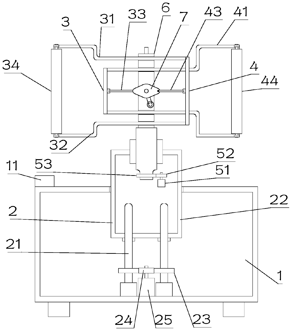
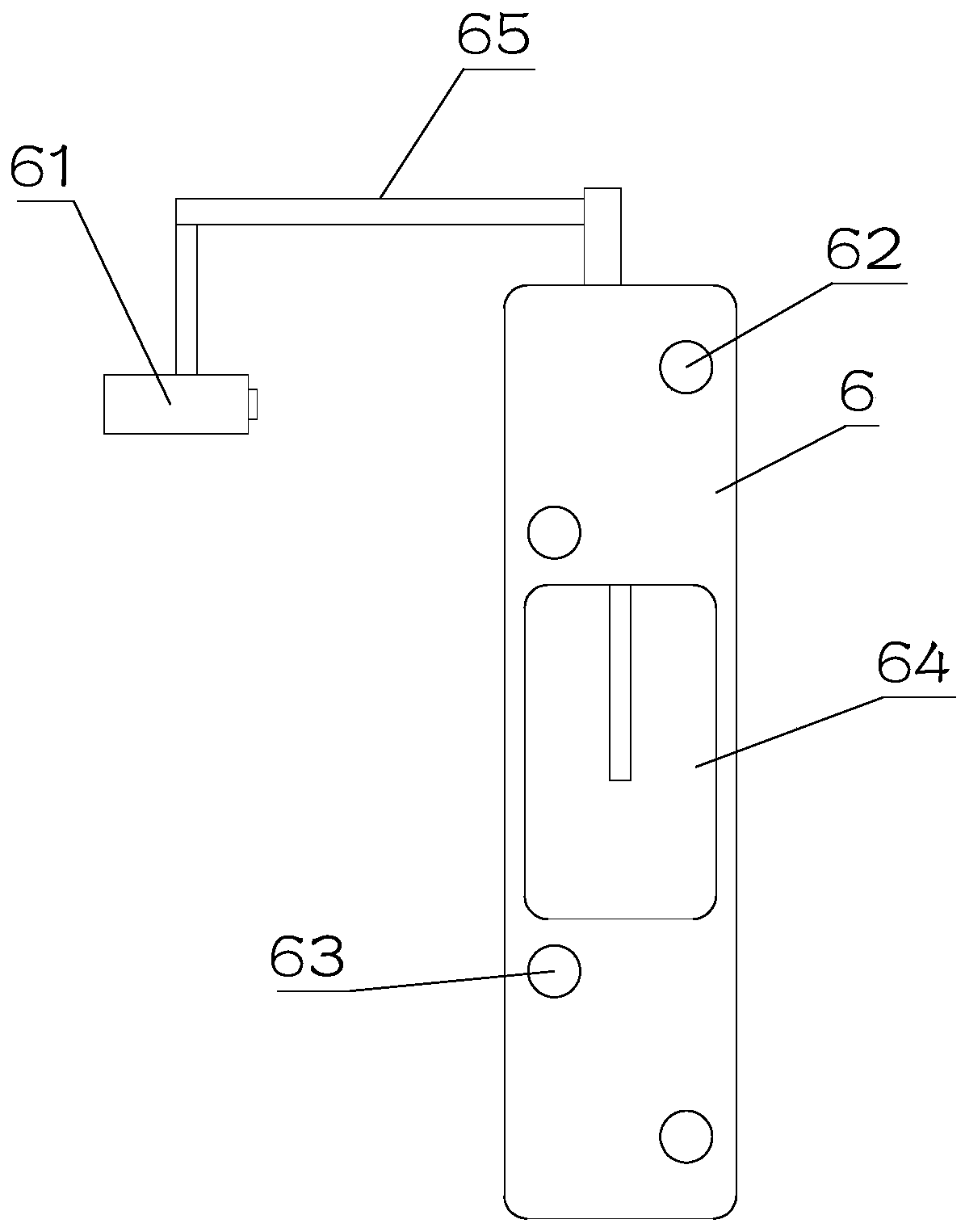
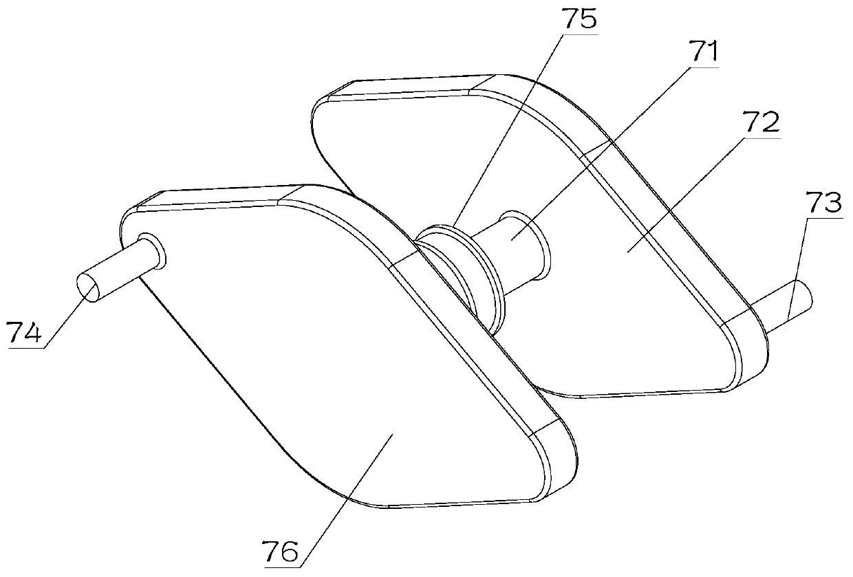
[0023] see Figure 1~3 , in Embodiment 1 of the present invention, an automatic control teaching demonstration device includes a base 1, a lifter 2 installed on the base 1, a support member 6 rotatably arranged on the lift assembly 2, and a left extension set on the support member 6. Out assembly 3 and right extension assembly 4, described left extension assembly 3 includes frame one 31 and connecting rod one 33, described right extension assembly 4 includes frame two 41 and connecting rod two 43, described frame one 31 and Frame 2 41 slides and passes through the through hole 1 62 and through hole 2 63 on the support member 6 respectively, and the frame 1 31 and frame 2 41 are respectively provided with a reel 34 and a reel at the ends of the support 6. Two 44, and the first reel 34 and the second reel 44 are curled with interconnected projection screens, the mounting groove 64 inside the support member 6 is equipped with a rotating assembly 7, and the rotating assembly 7 is ...

Embodiment 2

[0026] see Figure 1~3 The main difference between this embodiment 2 and embodiment 1 is that a pole 65 is fixedly installed on the support member 6, and a projector 61 is installed on the end of the pole 65 away from the support member 6, and the projector 61 is set for Projection on the projection screen.

[0027] A motor three is also arranged inside the installation slot 64 , and the motor three is in transmission connection with the pulley 75 on the rotating shaft 71 . The third motor provides power for the rotation of the rotating shaft 71 .

[0028] The bottom of the support member 6 is rotatably installed on the lifting assembly 2, which is convenient for adjusting the angle of the support member 6, thereby adjusting the angle of the projection screen.

[0029] The lifting assembly 2 is internally provided with a rotating assembly 5 that drives the supporting member 6 to rotate automatically. The rotating assembly 5 provides power for the supporting member 6 to rota...


PUM


Abstract

The invention discloses an automatic control teaching demonstration device, and relates to the technical field of teaching equipment. The device comprises a pedestal, a lifting component installed onthe pedestal in a lifting manner, a support piece rotationally arranged on the lifting component, and a left stretching component and a right stretching component arranged on the support piece, wherein the left stretching component comprises a first frame and a first connection rod; the right stretching component comprises a second frame and a second connection rod; the first frame and the secondframe correspondingly penetrate through a first through hole and a second through hole in the support piece in a sliding manner; a first reel and a second reel are correspondingly arranged at the endparts, far away from the support piece, of the first frame and the second frame; projection screens connected with each other are curled on the first reel and the second reel; a rotation component isinstalled on an installation slot in the support piece; the rotation component comprises a rotation shaft, a first drive disk and a second drive disk. The automatic control teaching demonstration device meets the requirements on different projection lengths, heights and angles, and is convenient to use.

Description

technical field [0001] The invention relates to the technical field of teaching equipment, in particular to an automatic control teaching demonstration device. Background technique [0002] In the teaching process, the teacher needs to impart some knowledge to the students. Since there are more students in each class, in order to make it convenient for all students to observe, traditionally, the teacher will draw graphics or knowledge points on the blackboard. With continuous development, people are gradually using multimedia teaching in the field of teaching. [0003] However, the size and area of ​​the screen cloth of the multimedia teaching projection in the prior art cannot be adjusted, so only certain information can be fixedly projected each time, and the projected area cannot be adjusted according to the size of the classroom, and cannot meet the needs of different teachers. Requirements, so it is necessary to design an automatic control teaching demonstration device...

Claims


Application Information

Patent Timeline
IPC IPC(8): G09B5/02F16M11/06F16M11/24F16M11/18G03B21/54G03B21/58
CPCF16M11/06F16M11/18F16M11/24G03B21/54G03B21/58G09B5/02
Inventor 姚树香张民旺
Owner 厦门软件职业技术学院
Features
  • R&D
  • Intellectual Property
  • Life Sciences
  • Materials
  • Tech Scout
  • Unparalleled Data Quality
  • Higher Quality Content
  • 60% Fewer Hallucinations
Learn More