Time synchronization method and system for SDN network of intelligent substation

A technology of time synchronization system and intelligent substation, which is applied in time division multiplexing system, transmission system, digital transmission system, etc., and can solve the problems of centralized processing of network protocols, network loops, broadcast storms, and data transmission in Ethernet switch networking. Packet error handling and other issues, to achieve the effect of improving access security, simplifying workload, and saving operation and maintenance costs

Active Publication Date: 2020-02-14
GLOBAL ENERGY INTERCONNECTION RES INST CO LTD +2
View PDF8 Cites 9 Cited by
  • Summary
  • Abstract
  • Description
  • Claims
  • Application Information

AI Technical Summary

Problems solved by technology

[0006] In order to solve the problems that the above-mentioned Ethernet switch network cannot perform centralized processing of network protocols, operation and maintenance management is troublesome, and when the problem of "flow table consis

Method used


Image

  • Time synchronization method and system for SDN network of intelligent substation
  • Time synchronization method and system for SDN network of intelligent substation
  • Time synchronization method and system for SDN network of intelligent substation

Examples


Example Embodiment

[0055] Example 1

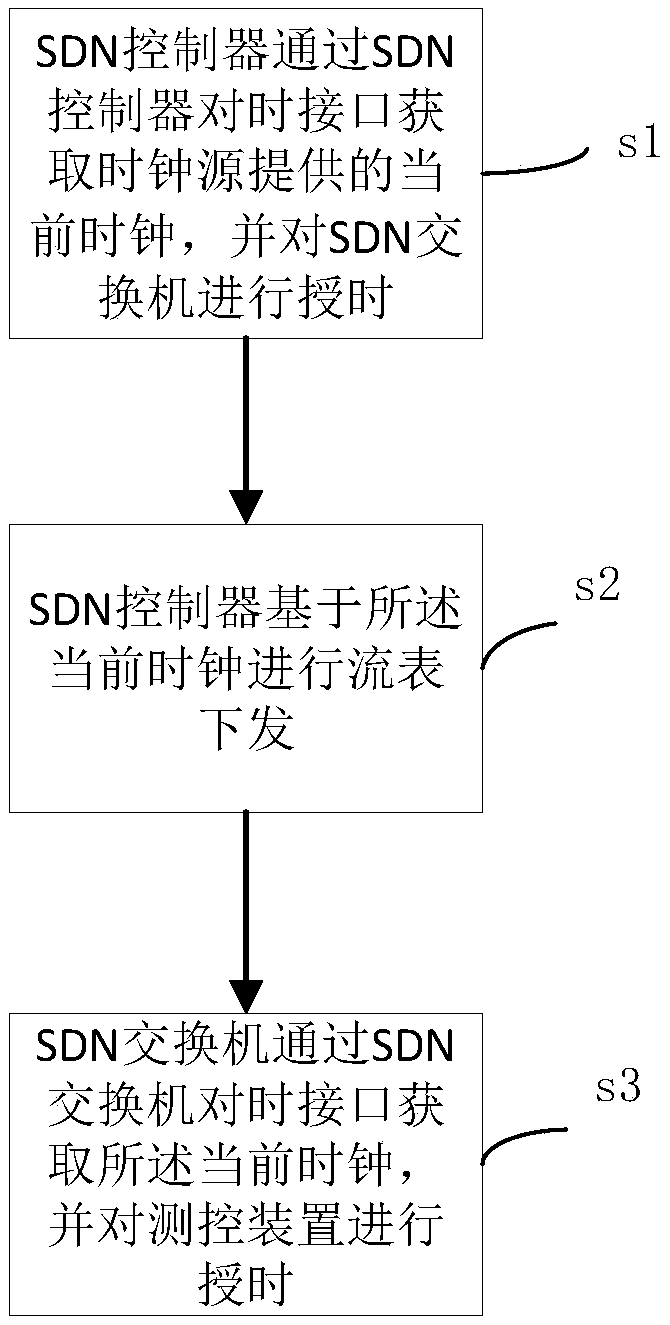
[0056] like figure 1 A time synchronization method for a smart substation SDN network is shown, including:

[0057] Step 1: The SDN controller obtains the current clock provided by the clock source through the SDN controller time synchronization interface, and performs time service to the SDN switch;

[0058] Step 2: The SDN controller issues the flow table based on the current clock;

[0059] Step 3: The SDN switch obtains the current clock through the time synchronization interface of the SDN switch, and performs time service to the measurement and control device.

[0060] The above-mentioned steps are explained and illustrated in detail below;

[0061] Specific instructions for step 1:

[0062] The SDN controller obtains the current clock provided by the clock source through the SDN controller timing interface, and the specific explanation for timing the SDN switch is as follows:

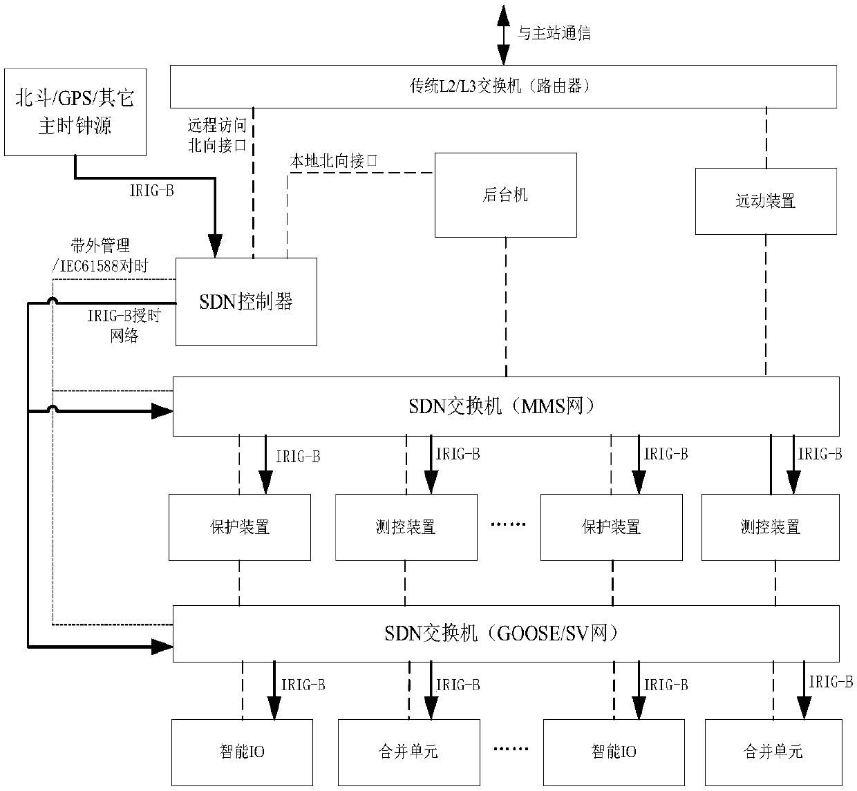
[0063] The SDN controller is the main clock of the entire SDN network...

Example Embodiment

[0088] Example 2

[0089] A time synchronization system for an intelligent substation SDN network, comprising:

[0090] Acquisition module: used for the SDN controller to obtain the current clock provided by the clock source through the SDN controller timing interface, and perform timing for the SDN switch;

[0091] Delivery module: used for the SDN controller to deliver the flow table based on the current clock;

[0092] Timing module: used for the SDN switch to obtain the current clock through the SDN switch timing interface, and to perform timing for the measurement and control device.

[0093] The acquisition module includes a first judging unit and a first timestamp adding unit;

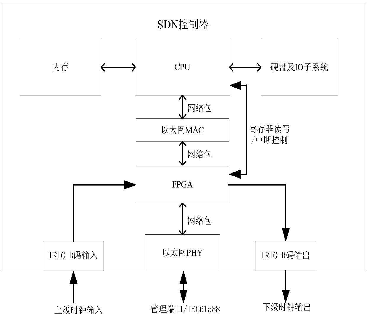
[0094] The first judging unit is used to judge whether the IRIG-B interface of the SDN controller is normal, if normal: the IRIG-B code clock input interface of the SDN controller obtains the clock source from the timing device, and outputs through the IRIG-B code The interface provides timin...


PUM


Abstract

The invention relates to a time synchronization method and system for an SDN network of an intelligent substation. The method comprises the following steps: the SDN controller acquires a current clockprovided by the clock source through the SDN controller time synchronization interface and performs time service on the SDN switch, the SDN controller issues a flow table based on the current clock,and the SDN switch acquires the current clock through the SDN switch time synchronization interface and performs time service on the measurement and control device. According to the time synchronization method and system for the SDN network of the intelligent substation, the SDN controller is introduced into the intelligent substation, a traditional Ethernet switch networking mode is replaced, centralized processing of network protocols can be carried out, the operation efficiency and convergence speed of complex protocols can be improved, and the looped network self-healing problem in the substation can be solved.

Description

technical field [0001] The invention relates to the technical field of power system communication and software-defined network, in particular to a time synchronization method and system for an intelligent substation SDN network. Background technique [0002] Software Defined Network (Software Defined Network, SDN) is a new innovative network architecture. Its core technology, OpenFlow, realizes flexible control of network traffic by separating the control plane of network equipment from the data plane. [0003] The smart substation adopts advanced, reliable, integrated, low-carbon, and environmentally friendly smart equipment. With the basic requirements of digitalization of the whole station information, networking of the communication platform, and standardization of information sharing, it automatically completes information collection, measurement, control, protection, measurement, and monitoring. and other copy functions, and can support substations with advanced functi...

Claims


Application Information

Patent Timeline
IPC IPC(8): H04J3/06H04L12/437
CPCH04J3/0667H04L12/437
Inventor 喻强虞跃刘川张刚吕立冬李炳林郭经红邓辉张增华孙晓艳王玮陶静黄在朝张浩姚启桂陈伟陈磊王向群沈文卜宪德田文峰姚继明
Owner GLOBAL ENERGY INTERCONNECTION RES INST CO LTD
Why Eureka
Try Eureka