Oral endoscope

An intraoral and speculum technology, applied in the field of intraoral endoscopes, can solve problems such as complex shapes, affecting information collection, and narrow lens observation range

Inactive Publication Date: 2020-02-21
马健
View PDF0 Cites 1 Cited by
  • Summary
  • Abstract
  • Description
  • Claims
  • Application Information

AI Technical Summary

Problems solved by technology

Patients can also understand the urgency of treatment. Physicians can clearly and intuitively see the situation inside the patient's mouth, so as to further discover the patient's oral lesions and take various treatment measures in time. The internal structure and shape are complex, and the length of the oral endoscope body is fixed, which seriously affects the collection of information. At the same time, the observation range of the fixedly connected lens is extremely narrow, and it is inconvenient to adjust the angle of the lens

Method used


Image

  • Oral endoscope
  • Oral endoscope
  • Oral endoscope

Examples


Embodiment 2

[0025] Embodiment 2: The difference between this embodiment and Embodiment 1 is that the handle 1 is provided with a non-slip rubber sleeve. For structures not mentioned in this embodiment, please refer to the description of Embodiment 1.

[0026] In this embodiment, the handle 1 is provided with a non-slip rubber sleeve to avoid free slipping between the doctor and the handle 1, causing secondary injuries to the patient, disrupting the doctor's work rhythm, thereby increasing the distance between the doctor and the handle 1. The friction force between them further improves the accuracy of detection. For the principles not mentioned in this embodiment, please refer to the description of Embodiment 1.

Embodiment 3

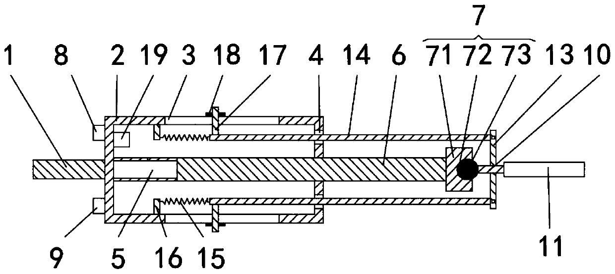
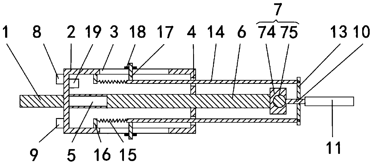
[0027] see image 3 , Embodiment 3: The difference between this embodiment and Embodiment 1 is that the rotating mechanism 7 includes a first support 74 and a rotating shaft 75 . Please refer to the description of Embodiment 1 for structures not mentioned in this embodiment.

[0028] In this embodiment, the right end of the push rod 6 is installed with a first support 74 , the first support 74 is rotatably connected with a rotating shaft 75 , and the connecting rod 10 is fixedly connected with the rotating shaft 75 .

[0029]Working principle: the connecting rod 10 drives the rotating shaft 75 to rotate with the first support 74 as the central axis. As the connecting rod 10 rotates upwards, the first connecting rod 13 on the lower side also rotates accordingly, driving the second connecting rod 14 to move, and the second connecting rod 14 moves. The second connecting rod 14 pulls the extension spring 15, and the extension spring 15 limits the movement of the rotating shaft 75 ...


PUM


Abstract

The invention discloses an oral endoscope. The oral endoscope comprises a handle; a shell is installed at the right end of the handle; square holes are symmetrically provided on upper and lower partsof the shell; round holes are symmetrically provided on upper and lower parts of a right surface of the shell; a first electric telescopic pole is installed on a right surface of an inner cavity of the shell; a push rod is installed at the right end of the first electric telescopic pole; a rotating mechanism is installed at the right end of the push rod; a connecting rod is installed at one end ofthe rotating mechanism; a mirror is installed at the right end of the connecting rod; a plurality of illumination lamps are provided on an outer edge of the mirror; and first connecting bars are installed on both upper and lower end surfaces of the connecting rod. The oral endoscope solves the problems of seriously affected information collection due to simplex structures of existing oral endoscopes incompatible with complex oral cavity structures and shapes and fixed lengths of oral endoscope bodies, as well as inconvenient lens angle adjustment due to extremely narrow observation ranges offixedly connected lenses.

Description

technical field [0001] The invention relates to the technical field of medical equipment, and the specific field is an oral cavity endoscope. Background technique [0002] At present, the number of patients in the Department of Stomatology is constantly increasing. The oral endoscope is one of the most important tools for oral examination. The oral endoscope has brought a new model for the examination and treatment of the oral cavity. When the patient's lesions are displayed in When in front of the patient, no further description or expertise is required. Patients can also understand the urgency of treatment, and doctors can clearly and intuitively see the situation inside the patient's mouth, so as to further discover the patient's oral lesions and take various treatment measures in time. The internal structure and shape are complex, and the length of the intraoral endoscope body is fixed, which seriously affects the collection of information. At the same time, the observa...

Claims


Application Information

Patent Timeline
Patent Type & Authority Applications(China)
IPC IPC(8): A61B1/247A61B1/06
CPCA61B1/06A61B1/247
Inventor 马健
Owner 马健
Why Eureka
Try Eureka