
Manual clamping mechanism for battery module

A clamping mechanism and battery module technology, which is applied in the directions of load hanging components, transportation and packaging, etc., can solve the problems that the clamping mechanism cannot realize the workpiece and the space is small.

Pending Publication Date: 2020-02-21
天永锂电自动化设备(太仓)有限公司
View PDF0 Cites 0 Cited by
  • Summary
  • Abstract
  • Description
  • Claims
  • Application Information

AI Technical Summary

Problems solved by technology

[0004] The problem to be solved in the present invention is that when the battery module is hoisted into the casing, the traditional clamping mechanism cannot realize the lifting function of the workpiece due to the narrow space between the battery modules and between the battery module and the casing

Method used


Image

  • Manual clamping mechanism for battery module
  • Manual clamping mechanism for battery module
  • Manual clamping mechanism for battery module

Examples


Embodiment Construction

[0021] The following will clearly and completely describe the technical solutions in the embodiments of the present invention with reference to the accompanying drawings in the embodiments of the present invention. Obviously, the described embodiments are only some, not all, embodiments of the present invention.

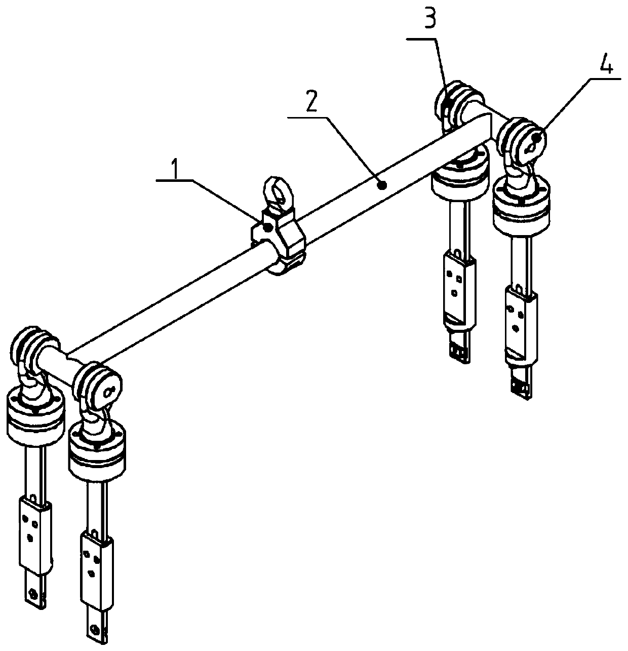
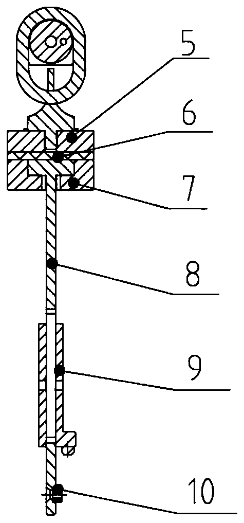
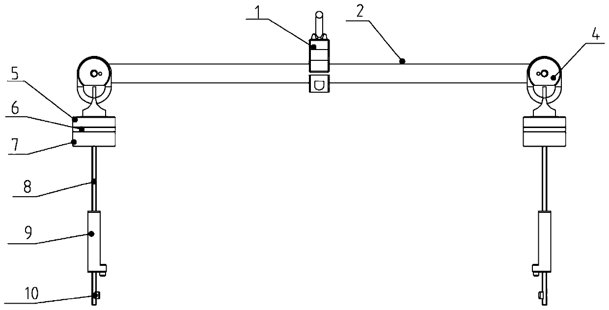
[0022] Such as Figure 1 to Figure 4 As shown, a battery module manual clamping mechanism provided by the present invention includes a hanging beam 2 and jaws 12. Both ends of the hanging beam 2 are respectively connected to the first connecting rod 11 and the second connecting rod 13. The first Two groups of jaws 12 are respectively installed on the connecting rod 11 and the second connecting rod 13, the two groups of jaws 12 on the first connecting rod 11 and the two groups of jaws 12 on the second connecting rod 13 are oppositely arranged, and the jaws 12 Including the universal lifting point 3, the universal lifting point 3 is fastened on the connecting rod throu...


PUM


Abstract

The invention discloses a manual clamping mechanism for a battery module. The manual clamping mechanism comprises a lifting beam. The two ends of the lifting beam are connected with clamping claw structures through a first connecting rod and a second connecting rod correspondingly. The clamping claw structures on the first connecting rod and the second connecting rod are oppositely arranged. Eachclamping claw structure comprises two sets of clamping claws, and clamp teeth are connected below the clamping claws. The manual clamping mechanism is suitable for clamping the battery module, the characteristics of the battery module are utilized, clamp teeth are plugged in auxiliary holes in the side face of the module, then bolt sliding blocks slide downwards along lifting arms, and lifting points are locked through baffles. The manual clamping mechanism for the battery module is characterized in that one abutting and double locking are achieved, safety of people in the lifting process is ensured, much moving space is not needed around a clamped workpiece, and the manual clamping mechanism is particularly suitable for lifting the battery module and assembling the battery module into a shell.

Description

technical field [0001] The invention relates to the technical field of clamping mechanisms, in particular to a manual clamping mechanism for battery modules. Background technique [0002] Commonly used manual clamping structures (that is, manual spreaders) generally have a scissors-type linkage mechanism, a pneumatic clamping mechanism, a vacuum suction cup, and the like. Whether it is the linkage mechanism with scissors difference or the pneumatic clamping mechanism, it is required to leave enough room for movement around the workpiece to be clamped; and the above clamping mechanisms have certain restrictions on the way the workpiece is fed and the environment for discharging it. limit. [0003] In the field of new energy assembly, when lifting the battery module into the casing, due to the narrow space between the battery modules and between the battery module and the casing, the traditional clamping mechanism cannot realize the lifting function of the workpiece. Conten...

Claims


Application Information

Patent Timeline
IPC IPC(8): B66C1/66
CPCB66C1/66
Inventor 荣俊林
Owner 天永锂电自动化设备(太仓)有限公司
Learn More