Upper air inlet combustor

A burner and ring gas technology, applied in the direction of burners, gas fuel burners, combustion methods, etc., can solve the problems of affecting gas combustion conditions, insufficient gas combustion, easy to produce yellow flames, etc., and achieve short and stable flames and uniform flame, reducing the effect of kinetic energy loss

Pending Publication Date: 2020-02-25
NINGBO FOTILE KITCHEN WARE CO LTD
View PDF2 Cites 0 Cited by
  • Summary
  • Abstract
  • Description
  • Claims
  • Application Information

AI Technical Summary

Problems solved by technology

[0002] The existing burner is a gas system commonly used in household gas stoves and integrated stoves. Its main purpose is to provide heat to food or water in the appliance. There are two types of wind burners. The existing upward air intake burner generally adopts multi-nozzle design, and the ejector pipe is generally short. Flame, away from the flame; in order to solve the above problems, the Chinese invention patent "A Kind of Updraft High-Power Burner" with the patent number ZL201620644143.0 (the authorized announcement number is CN205746832U) discloses a burner that passes through the Y-shaped distribution in the burner head seat. The Venturi conical injection tube design effectively prolongs the length of the injection tube so that the disposable air can be fully premixed with the gas to ensure that the gas can be fully combusted. There are combustion fire holes, the shape of the holes is circular, evenly distributed around the outer ring surface, and there are also combustion fire holes on the inner slope, the combustion fire holes are evenly distributed around the inner slope, forming two concentric fire rings inside and outside.

Method used


Image

  • Upper air inlet combustor
  • Upper air inlet combustor
  • Upper air inlet combustor

Examples


Embodiment Construction

[0039] The present invention will be further described in detail below in conjunction with the accompanying drawings and embodiments.

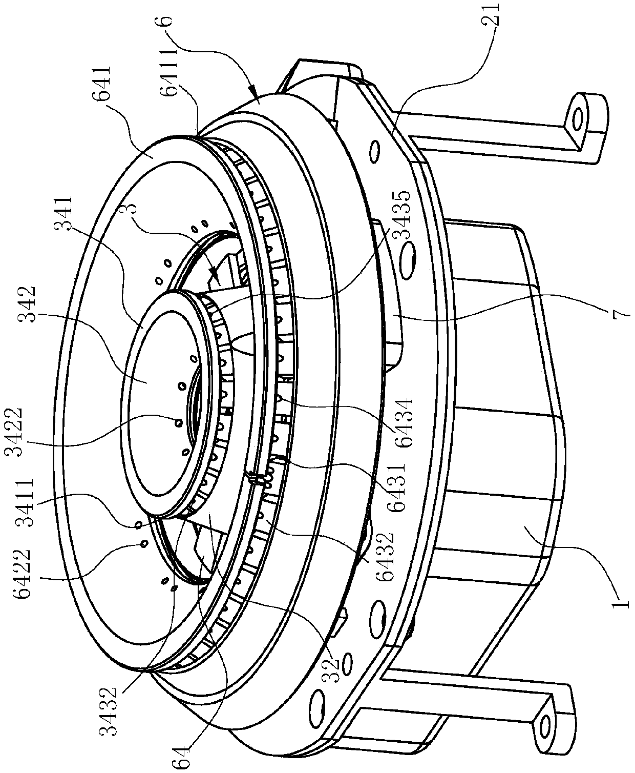
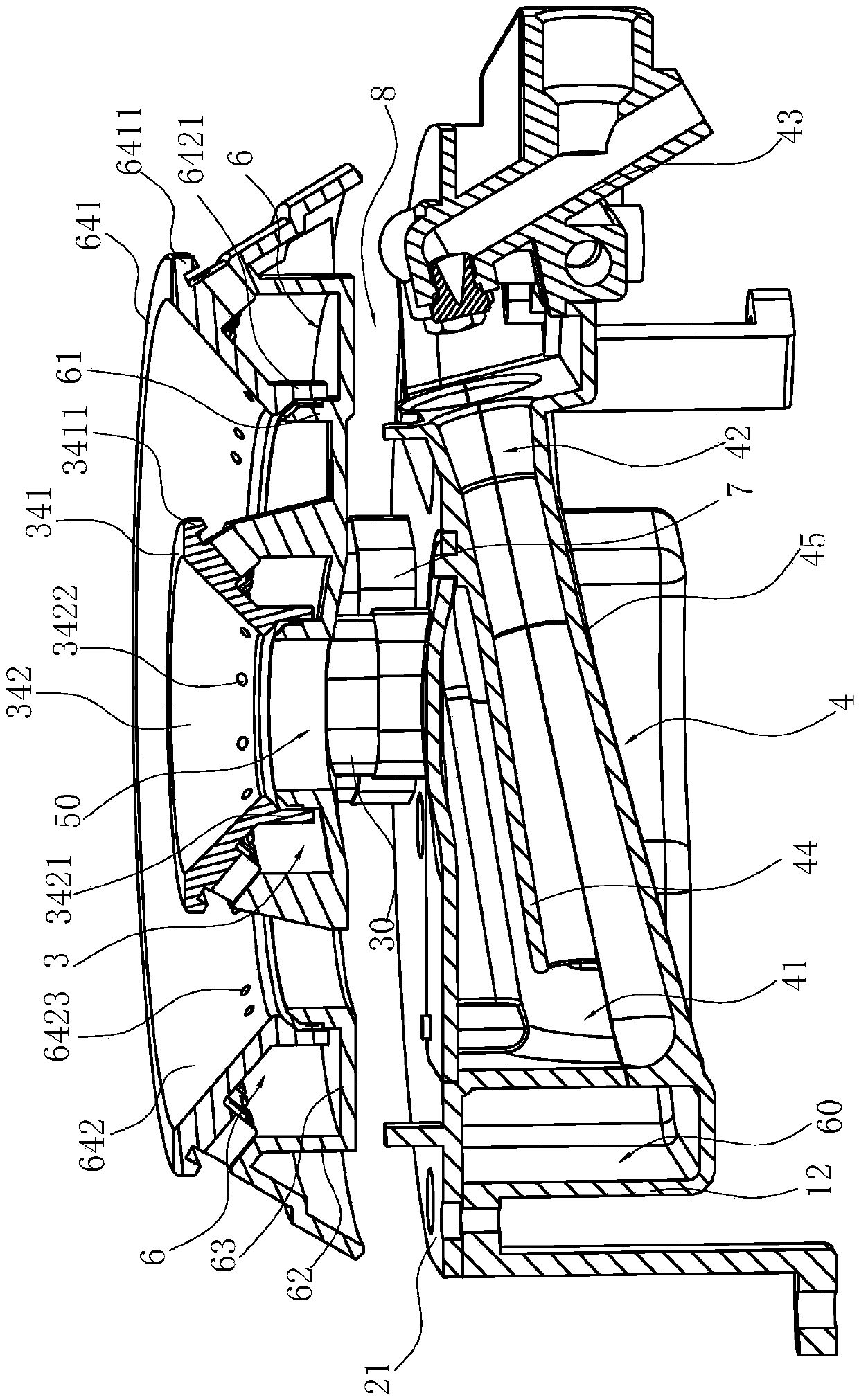
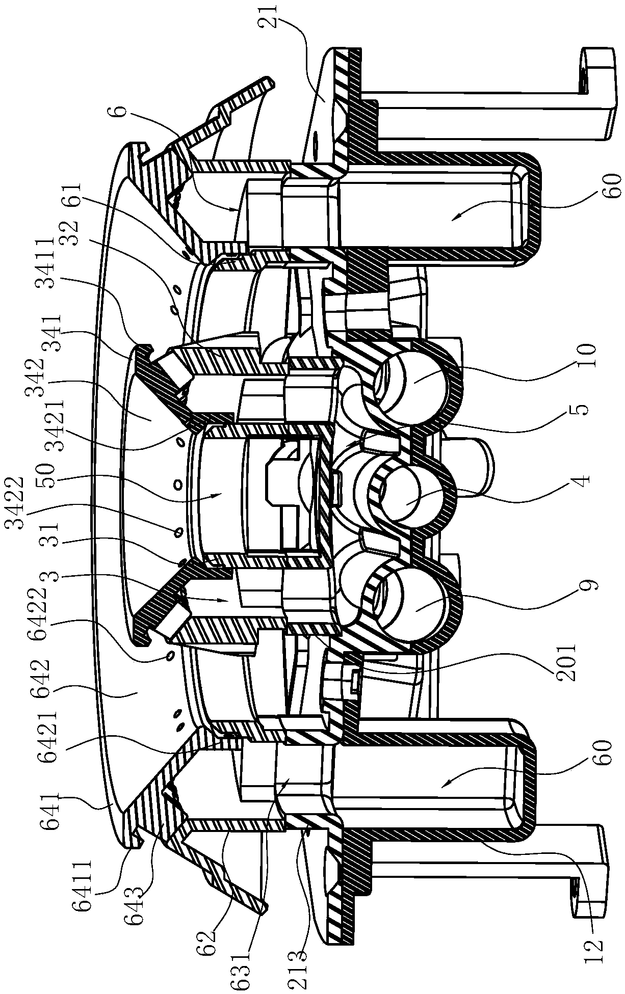
[0040] Such as Figure 1-11 As shown, it is the best embodiment of the present invention, the upper air intake burner can be applied to the traditional upper air intake burner and can also be applied to the Italian Sabaf burner such as Europe, including a base 1, which has The first concave cavity 11 located in the center; the connecting body 2 arranged on the base 1, the connecting body 2 includes a plate body 21, and the central position of the plate body 21 corresponds to the first concave cavity 11 and has a vertical inner ring gas Channel 211 and the inner ring gas mixing chamber 3 arranged above the inner ring gas channel 211. The inner ring gas mixing chamber 3 of this embodiment includes an annular inner ring wall surface 31 and an outer ring wall surface 32 arranged concentrically at intervals and connecting The bottom wall 33 of the...


PUM


Abstract

The invention relates to an upper air inlet combustor. The upper air inlet combustor is characterized by comprising a base with a first cavity, a connecting body located above the base, an inner ringmixing chamber and an inner ring ejector tube, wherein the inner ring ejector tube is transversely formed in the first cavity in a downward inclined manner from top to bottom and forms a buffer cavitywith the lower surface of the connecting body, the gas outlet end of the inner ring ejector tube is in fluid communication with an inner ring gas passage through the buffer cavity, and the air inletend of the inner ring ejector tube is fitted with an inner ring nozzle. Compared with the prior art, the upper air inlet combustor has the advantages that the buffer cavity is provided with a buffer space for the primary air/gas mixture lead out from air outlet end of the inner ring ejector tube, uniform primary air after the buffer cavity is subjected to mixing of primary air, gas and primary airare prevented from colliding with each other due to converge from different directions, and the uniformity of primary air and gas mixing is further improved, so that the flame of the upper air inletcombustor is short, uniform and powerful.

Description

technical field [0001] The invention relates to a burner for a gas cooker, in particular to an upward air-intake burner for a cooker. Background technique [0002] The existing burner is a gas system commonly used in household gas stoves and integrated stoves. Its main purpose is to provide heat to food or water in the appliance. There are two types of wind burners. The existing upward air intake burner generally adopts multi-nozzle design, and the ejector pipe is generally short. Flame, away from the flame; in order to solve the above problems, the Chinese invention patent "A Kind of Updraft High-Power Burner" with the patent number ZL201620644143.0 (the authorized announcement number is CN205746832U) discloses a burner that passes through the Y-shaped distribution in the burner head seat. The Venturi conical injection tube design effectively prolongs the length of the injection tube so that the disposable air can be fully premixed with the gas to ensure that the gas can b...

Claims


Application Information

Patent Timeline
Patent Type & Authority Applications(China)
IPC IPC(8): F23D14/04F23D14/46F23D14/58F23D14/64F23D14/26
CPCF23D14/04F23D14/26F23D14/46F23D14/58F23D14/64F23D2900/14062
Inventor 卢华师
Owner NINGBO FOTILE KITCHEN WARE CO LTD
Why Eureka
Try Eureka