Upward air inlet burner and kitchen range using upward air inlet burner

A burner and injector technology, applied in the direction of burners, gas fuel burners, combustion methods, etc., can solve the problems of uneven gas pressure, increase the ejection resistance, and cannot be cleared, and achieve stable and uniform flame, The effect of reducing kinetic energy loss and improving suction rate

Pending Publication Date: 2020-05-08
NINGBO FOTILE KITCHEN WARE CO LTD
View PDF2 Cites 0 Cited by
  • Summary
  • Abstract
  • Description
  • Claims
  • Application Information

AI Technical Summary

Problems solved by technology

However, the traditional completely upward air-intake burner is realized through the gap between the air-mixing chamber and the base when the primary air is supplemented. The problem caused by this is that there is a gap between the air-mixing chamber and the base. After the installation screws are installed, the installation screws can be seen from the outside of the burner, resulting in an unattractive appearance of the burner
Moreover, after a gap is set between the base and the air mixing chamber, the overflow will flow through the gap into the base and the circular basin-shaped main body located under the panel, that is, the term "bottom cup". There are many problems in user maintenance and cleaning. Inconvenient, and if the overflow is not cleaned for a long time, it will affect the normal use of the burner
In addition, the structure of the "bottom cup" makes the outlet of the ejector tube and the mixed gas channel connect with a sharp bend, which significantly increases the ejection resistance. Such a design is such as the Chinese patent No. ZL201120156854.0 (authorized announcement No. CN202082922U). The utility model patent "Gas Burner" has a poor ejection effect. At the same time, the primary air supplied by this type of upward air-intake burner from above the panel enters the "bottom cup" using the negative pressure generated by the nozzle jetting gas, which is easy The air flow distribution of the primary air is uneven, which affects the primary air coefficient to a certain extent, so that the pressure of the gas flowing out of the fire holes arranged along the circumferential direction of the outer ring fire cover or the inner ring fire cover is uneven, resulting in the formation of the outer ring fire cover. The flame of the inner ring fire produced by the outer ring fire or the inner ring fire cover is not uniform. At the same time, the second ejector tube and the first ejector tube of this type of burner are integrated with the "bottom cup" or integrated with the "bottom cup". The separate setting of the bottom cup, whether it is the problem of poor ejection effect caused by the integrated setting with the "bottom cup", or the safety hazard caused by the air leakage caused by the seam caused by the separate setting of the bottom cup , both need to make further improvements to the existing upward air-intake burners
In addition, there is a class of Chinese invention patent application publication "A Multi-Nozzle, Large Flow, and Completely Updraft Embedded Burner for Household Gas Stove" (publication number CN101446415A) such as the application number of which is 200810220263.8. The inner and outer nozzles corresponding to the ring ejector are respectively arranged on both sides within the diameter range of the burner, which can effectively improve the limitation of the short length of the ejector tube, and at the same time realize the independent adjustment of the inner and outer fires, and the combustion power is relatively large , the pursuit of high-power up-inlet burners has become the mainstream trend, but because the inner and outer ring ejectors are still set in the "bottom cup", the overall height of the burner is still high, and the overall aesthetics is poor

Method used


Image

  • Upward air inlet burner and kitchen range using upward air inlet burner
  • Upward air inlet burner and kitchen range using upward air inlet burner
  • Upward air inlet burner and kitchen range using upward air inlet burner

Examples


Embodiment 1

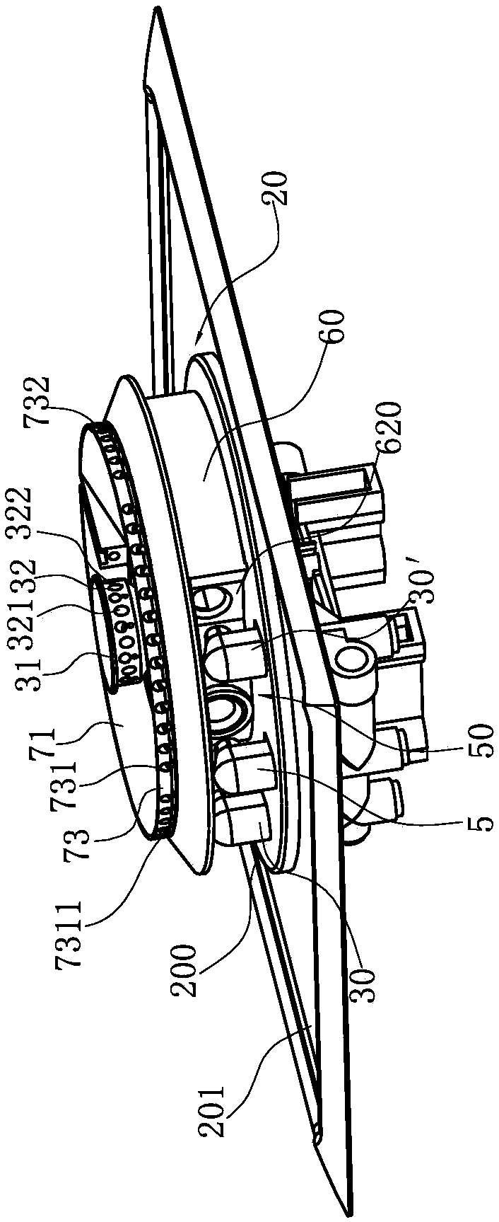
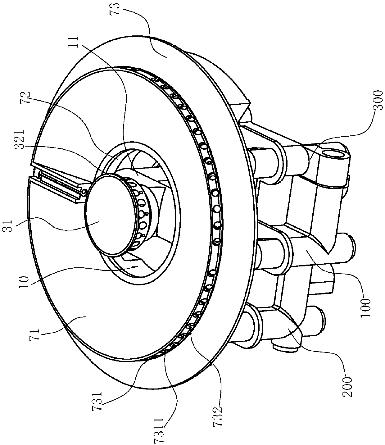
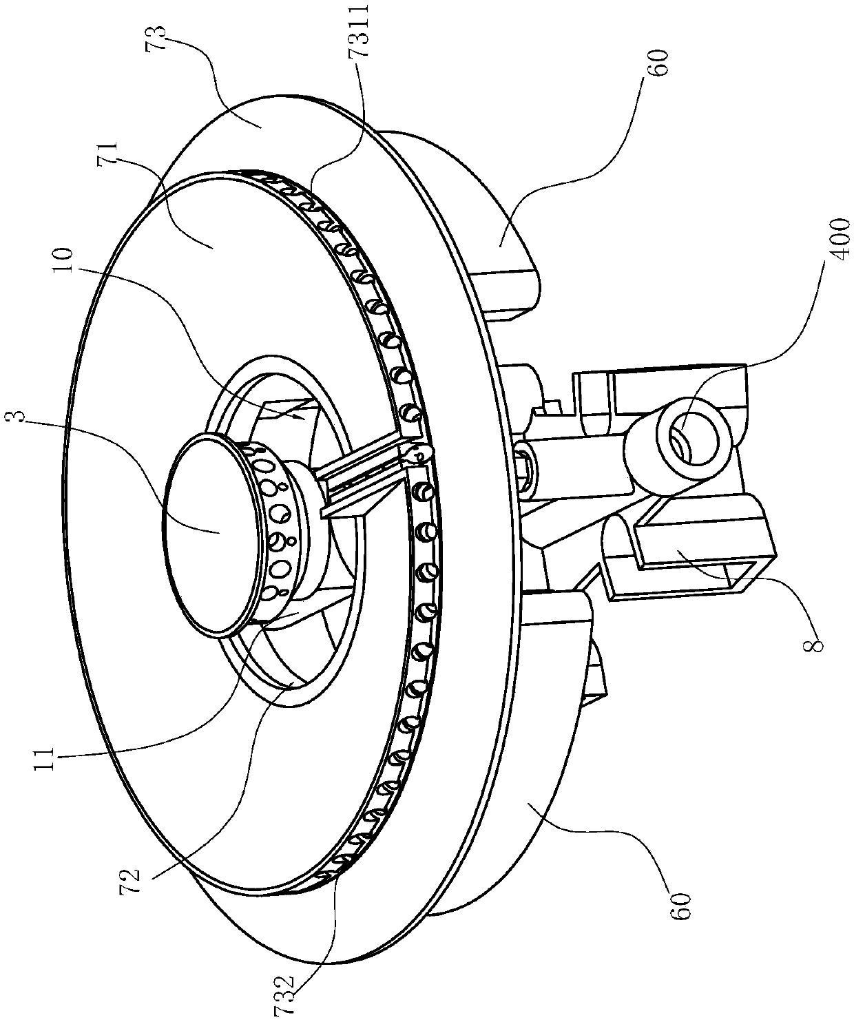
[0064] Such as Figure 1-9 Shown is the preferred embodiment of this embodiment. The upper air intake burner of this embodiment includes a first injection tube 2, a base 11 surrounding the tube wall of the first injection tube 2, and a base 11 surrounding the tube wall of the first injection tube 2. The buffer chamber 4 formed by the gap between the periphery of the tube wall of the shooter 2 and the base 11, and the first fire cover 3 arranged above the central position of the base 11, and a fire cover 3 is formed between the first fire cover 3 and the base 11 The first gas mixing chamber 1 located in the center, the gas outlet end 23 of the first injection tube 2 is in fluid communication with the first gas mixing chamber 1 through the buffer chamber 4, and the gas inlet end 24 of the first injection tube 2 is fitted with The first injector 5, the buffer chamber 4 effectively increases the length of the first injection pipe 2, and the setting of the buffer chamber 4 can mak...

Embodiment 2

[0070] Such as Figure 10-20 As shown, the structure is basically the same as that of Embodiment 1, the only difference is that the base 11 is cross-shaped, including a transverse portion 111 and a vertical portion 112 connected to each other, and the transverse portion 111 of the base 11 surrounds the first ejector tube 2 Outside the tube wall; the vertical part 112 of the base 11 is divided into the upper vertical part 1111 above the horizontal part 111 of the base 11 and the upper vertical part 1111 below the horizontal part 111 of the base 11 by the tube wall of the first injection tube 2 The lower vertical part 1112, the lower vertical part 1112 is in communication with the upper vertical part 1111; since the first ejector tube 2 is completely enclosed in the transverse part 111 of the base 11, due to processing restrictions, the first ejector tube Shooting tube 2 can not be done too long, for this reason base 11 is cross-shaped and then can make up for the above-mentione...

Embodiment 3

[0072] Such as Figures 21 to 30 As shown, the structure is basically the same as that of Embodiment 1, the only difference is that the base 11 is in an inverted T shape, has a horizontal tube 111 and a vertical tube 112 that communicate with each other, and the horizontal tube 111 surrounds the first injection tube 2 Outside the pipe wall, the inlet of the horizontal pipe 111 is the air inlet port 24, the end of the horizontal pipe 111 is a blind end, and the air outlet end 23 of the first ejector pipe 2 is close to the blind end; and the first fire cover 3 , covering the vertical pipe 112 to form the first air mixing chamber 1 in the center. Moreover, the inner wall of the horizontal tube 111 of the base 11 has a spiral rib 4″ and forms a spiral passage, the initial end 41 of the spiral passage communicates with the gas outlet end 23 of the first injection pipe 2, and the terminal end 42 of the spiral passage communicates with the first gas mixture. Chamber 1. Preferably, t...


PUM


Abstract

The invention relates to an upward air inlet burner. The upward air inlet burner is characterized by comprising a first ejector tube, a base surrounding the outside of the tube wall of the first ejector tube, a buffer cavity surrounding the tube wall of the first ejector tube and formed by a gap between the periphery of the tube wall of the first ejector tube and the base and a first burner cap arranged at the center position of the base, and a first gas mixing chamber at the center is formed between the first burner cap and the base; and the gas outlet end of the first ejector tube is in fluid communication with the first gas mixing chamber through the buffer cavity, and a first ejector is arranged at the gas inlet end of the first ejector tube in a matched mode. Compared with the prior art, the upward air inlet burner has the advantages that the first ejector tube is arranged in the base and the buffer cavity is arranged, the buffer cavity effectively increases the length of the first ejector tube, and meanwhile, the buffer cavity provides a buffer space to a primary air / gas mixture ejected from the gas outlet end of the first ejector tube.

Description

technical field [0001] The invention relates to a burner for a gas cooker, in particular to an upward air-intake burner for a cooker with multiple nozzles. Background technique [0002] At present, many gas cookers have begun to use fully upward air-intake burners. Since the complete upward air-intake burners burn, the primary and secondary air required for combustion come from the upper part of the cooker panel, so the chassis of the gas cooker It can be fully sealed. Compared with the traditional bottom air intake structure burner, the completely upward air intake burner is not only safer to use, but also can well solve the problem of stove flameout caused by opening and closing the cabinet door. However, the traditional completely upward air-intake burner is realized through the gap between the air-mixing chamber and the base when the primary air is supplemented. The problem caused by this is that there is a gap between the air-mixing chamber and the base. After the moun...

Claims


Application Information

Patent Timeline
Patent Type & Authority Applications(China)
IPC IPC(8): F23D14/04F23D14/26F23D14/46F23D14/58F23D14/64F23L9/00
CPCF23D14/04F23D14/26F23D14/46F23D14/58F23D14/64F23L9/00
Inventor 兰华
Owner NINGBO FOTILE KITCHEN WARE CO LTD
Why Eureka
Try Eureka