sheet metal cutter

A metal sheet cutting technology, applied in the direction of hand-held metal shearing equipment, metal processing equipment, shearing devices, etc., can solve the problems of not being straight enough, deformation, and fixed incision, and achieve simple operation, convenient use, and improved incision The effect of uniformity

Active Publication Date: 2021-03-09
XUZHOU LISTON IND DESIGN CO LTD
View PDF1 Cites 0 Cited by
  • Summary
  • Abstract
  • Description
  • Claims
  • Application Information

AI Technical Summary

Problems solved by technology

[0002] At present, metal sheets are generally used for the skin of steel exhibits and iron boxes. Due to the different areas and shapes of the sheets to be used, especially when making customized products, the shape is even more uncertain, so it is necessary to cut the sheets In the above occasions, the thickness of the metal sheet is mainly between 0.2-4mm. At the same time, the surface of the sheet is smooth, and its wall thickness is relatively thin. There will be deformation at the position of the cut mark, and the positioning is inconvenient. The common method is to manually control the scissors. Cutting, it is impossible to fix the thin plate on both sides of the cut mark, the cutting edge is not neat and straight enough, during the cutting process, the barbs that appear are easy to hurt the operator, and the existing ones only fix the thin plate The clamping device can only fix the thin plate as a whole, and cannot be fixed on both sides of the incision. For example, the publication number CN206702314U discloses a cutting and fixing device, which is characterized in that it includes a square frame and is arranged on the four corners of the square frame. Four supporting columns on the top, the four supporting columns include two left supporting columns arranged at the left two ends of the square frame and two right supporting columns arranged at the right two ends of the square frame, each The top of the left supporting column is provided with a left U-shaped positioning groove opening to the right, and the top of each of the right supporting columns is provided with a right U-shaped positioning groove opening to the left. The U-shaped positioning groove and the U-shaped positioning groove on the right side are arranged on the same plane. Although the device can fix and clamp the iron plate, it lacks pressure and fixation on both sides of the incision, and the complete deformation of the incision is prone to occur, which affects the subsequent masking process. skin coverage

Method used


Image

  • sheet metal cutter
  • sheet metal cutter
  • sheet metal cutter

Examples


Embodiment Construction

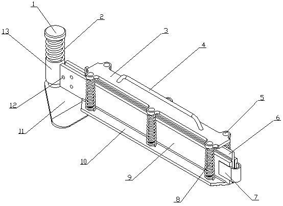
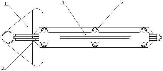
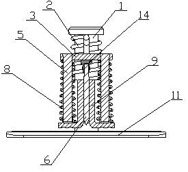
[0017] A kind of sheet metal cutter of the present invention is realized in this way, consists of guide post (1), return spring (2), driving plate (3), driving handle (4), sliding rod (5), cutting knife (6) , connecting arm (7), support spring (8), guide plate (9), pressure plate (10), base (11), connecting screw (12), guide sleeve (13), knife seat (14), fixed sleeve ( 15), press groove (16) and connecting plate (17), one end of the guide column (1) is vertically fixed on the base (11), and the other end of the guide column (1) is provided with a limiting plate, so The base (11) is an isosceles triangular plate structure, the bottom of the base (11) is a slope, the guide sleeve (13) is placed on the guide column (1), and the guide sleeve (13) can be rotated , the guide sleeve (13) is slidable, the return spring (2) is set on the guide column (1), one end of the return spring (2) is connected with the limit plate, and the return spring (2) The other end is connected with the g...


PUM


Abstract

The invention discloses a metal thin plate cutter which can press and fix both sides of a thin plate incision by a pressing plate, so as to improve the evenness of the incision. It can realize multi-angle cutting of the metal sheet without moving the metal sheet or the cutter. It is characterized in that one end of the guide column is vertically fixed on the base, and the other end of the guide column is placed on the limit plate, and the base is Isosceles triangle plate structure, the bottom edge of the base is a slope, the guide sleeve is placed on the guide column, the guide sleeve can be rotated, the guide sleeve can slide, the reset spring is placed on the guide column, the One end of the return spring is connected with the limit plate, the other end of the return spring is connected with the guide sleeve, the connecting plate is fixed on the outer side wall of the guide sleeve, and one end of the two guide plates is connected by fixing screws and The two sides of the plate are connected, and the two straight plate parts of the connecting arm are respectively connected with the other ends of the two guide plates.

Description

technical field [0001] The invention relates to a metal sheet cutter, which relates to a cutter for cutting metal sheets, and belongs to the field of metal processing. In particular, it relates to a thin plate cutter which presses and fixes both sides of the cut of the thin plate by means of a pressing plate to improve the uniformity of the cut. Background technique [0002] At present, metal sheets are generally used for the skin of steel exhibits and iron boxes. Due to the different areas and shapes of the sheets to be used, especially when making customized products, the shape is even more uncertain, so it is necessary to cut the sheets In the above occasions, the thickness of the metal sheet is mainly between 0.2-4mm. At the same time, the surface of the sheet is smooth, and its wall thickness is relatively thin. There will be deformation at the position of the cut mark, and the positioning is inconvenient. The common method is to manually control the scissors. Cutting,...

Claims


Application Information

Patent Timeline
Patent Type & Authority Patents(China)
IPC IPC(8): B23D29/00B23D29/02B23D33/02B23D35/00
CPCB23D29/005B23D29/026B23D33/02B23D35/001B23D35/005
Inventor 不公告发明人
Owner XUZHOU LISTON IND DESIGN CO LTD
Why Eureka
Try Eureka