China railway high-speed train multifunctional luminous decorative cover plate structure

A technology of plate structure and EMU, applied in the field of multi-functional luminous decorative cover plate structure of EMU, can solve the problems of economic loss, maintenance difficulty, increase maintenance cost and maintenance time, etc., to improve practicability, facilitate observation, disassembly and assembly convenient effects

Pending Publication Date: 2020-02-28
CRRC CHANGCHUN RAILWAY VEHICLES CO LTD
View PDF0 Cites 2 Cited by
  • Summary
  • Abstract
  • Description
  • Claims
  • Application Information

AI Technical Summary

Problems solved by technology

At present, the side wall panels and side roof panels in the bullet train sightseeing area are plugged in. The biggest disadvantage of this structure is that it is difficult to maintain when the sunshade roller shutter mechanism installed on the side wall panels breaks down.
At the same time, the sunshade roller shutter mechanism is one of the vulnerable parts in the interior decoration parts of the sightseeing area. When the original structure is repaired and replaced by the roller shutter mechanism, it is necessary to remove all the side roof panels and side wall panels to disassemble and repair the roller shutter mechanism. Increased maintenance cost and maintenance time, seriously affecting the operation time of EMUs and causing great economic losses

Method used


Image

  • China railway high-speed train multifunctional luminous decorative cover plate structure
  • China railway high-speed train multifunctional luminous decorative cover plate structure
  • China railway high-speed train multifunctional luminous decorative cover plate structure

Examples


Embodiment Construction

[0098] In order to enable those skilled in the art to better understand the technical solutions of the present invention, the present invention will be further described in detail below in conjunction with the accompanying drawings.

[0099] see Figure 1 to Figure 11 shown;

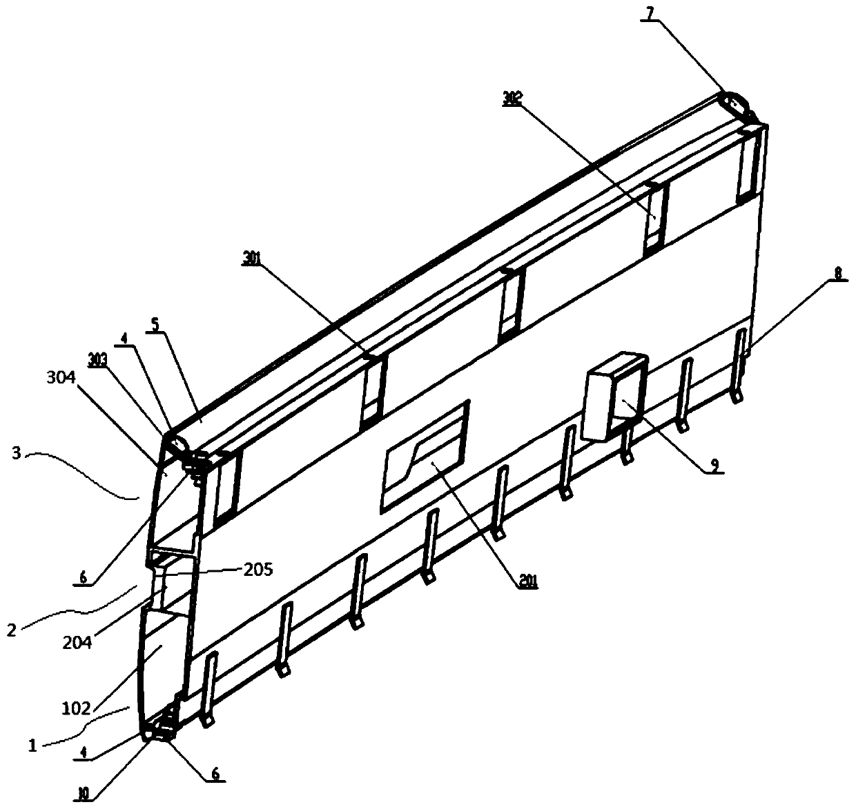
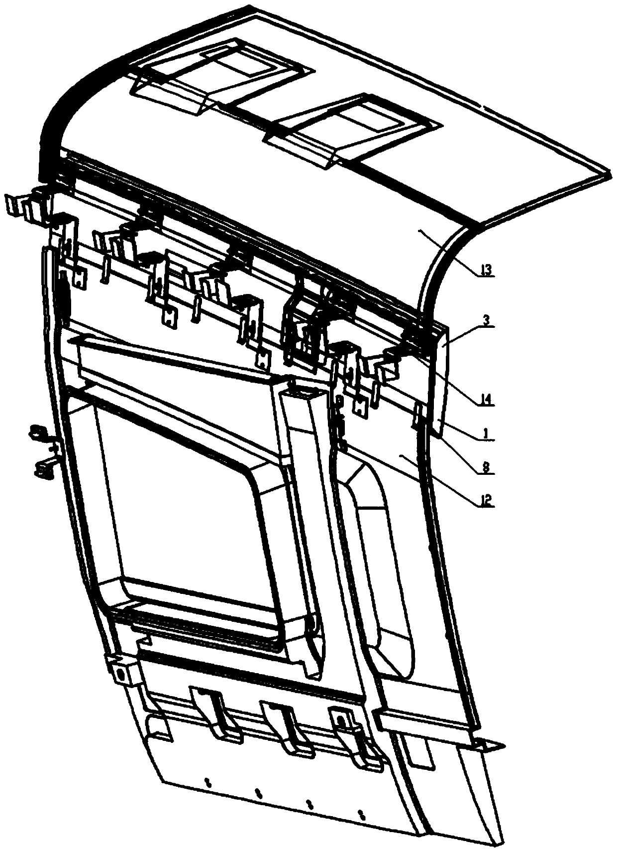
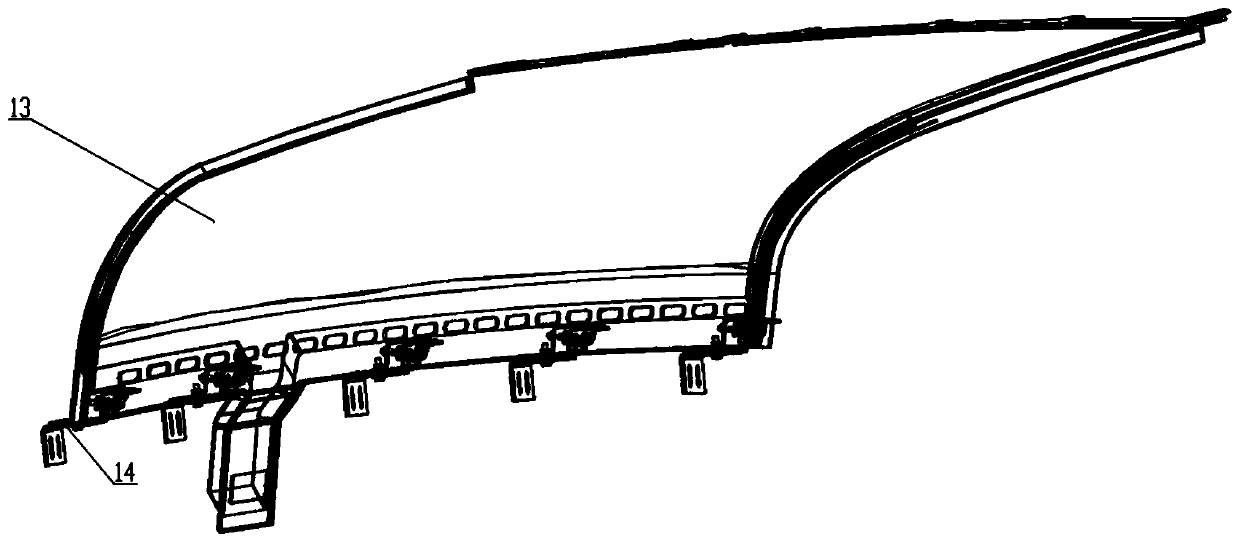
[0100] The multi-functional luminous decorative cover plate structure of the EMU of the present invention is assembled with the EMU side wall panel 12 and the side roof plate 13, and the luminous decorative cover plate structure mainly includes:

[0101] The upper cavity body 3, the middle cavity body 2 and the lower cavity body 1 are fixedly connected as an integral structure;

[0102] An upper cavity 304 extending along the length direction of the upper cavity body 3 is formed inside the upper cavity body 3;

[0103] A medium cavity 204 extending along the length direction of the medium cavity body 2 is formed inside the medium cavity body 2;

[0104] A lower cavity 102 extending along the length di...


PUM


Abstract

The invention discloses a China railway high-speed train multifunctional luminous decorative cover plate structure. The luminous decorative cover plate structure is assembled with a side wall plate and a side top plate of a China railway high-speed train, and comprises an upper cavity body, a middle cavity body and a lower cavity body, an upper part lamp body structure, a lower part lamp body structure and a seat display structure, wherein the upper cavity body, the middle cavity body and the lower cavity body are fixedly connected to be of an integrated structure; and the upper part lamp bodystructure is integrated at the upper end of the upper cavity body, the lower part lamp body structure is integrated at the lower end of the lower cavity body, and the seat display structure is formedon the middle cavity body. The luminous decorative cover plate structure solves the technical problem of difficult maintenance of inner roller shutters after installation of the side top plate and the side wall plate in a sightseeing area, adopts a decorative cover plate connection mode, ensures that dismounting and mounting are convenient, and the maintenance can be carried out after the decorative cover plate structure needs to be dismounted integrally; and lamp bodies are arranged at the corresponding positions of the upper cavity body and the lower cavity body, the lamp bodies can be usedas light sources, and meanwhile, seat displays are arranged on the middle cavity body, so that passenger observation is facilitated.

Description

technical field [0001] The invention relates to the technical field of interior design of rail transit vehicles, in particular to a multi-functional luminous decorative cover plate structure for an EMU. Background technique [0002] As one of the important carriages in the EMU sightseeing area, the structural tone of its interior decoration is particularly important. At present, the side wall panels and side roof panels in the bullet train sightseeing area are plugged in. The biggest disadvantage of this structure is that it is difficult to maintain when the sunshade roller shutter mechanism installed on the side wall panels breaks down. At the same time, the sunshade roller shutter mechanism is one of the vulnerable parts in the interior decoration parts of the sightseeing area. When the original structure is repaired and replaced by the roller shutter mechanism, it is necessary to remove all the side roof panels and side wall panels to disassemble and repair the roller shu...

Claims


Application Information

Patent Timeline
Patent Type & Authority Applications(China)
IPC IPC(8): B61D17/18B61D29/00B60Q3/20
CPCB60Q3/20B61D17/18B61D29/00
Inventor 夏东伟高义超李鹏飞杜乐于淼
Owner CRRC CHANGCHUN RAILWAY VEHICLES CO LTD
Why Eureka
Try Eureka