Novel mobile power supply

A mobile power supply, a new type of technology, applied in the field of power supply, can solve the problems of difficult maintenance of solar panels, solar mobile power supply cannot be easily disassembled, etc., to achieve the effect of convenient maintenance and replacement, faster charging speed, and avoid mutual wear

Inactive Publication Date: 2017-02-22
CHENGDU YANXINGGUO TECH CO LTD
View PDF0 Cites 0 Cited by
  • Summary
  • Abstract
  • Description
  • Claims
  • Application Information

AI Technical Summary

Problems solved by technology

[0004] Based on the above technical problems, the present invention provides a new type of mobile power supply, thereby solving the technical problems that the existing solar mobile power supply cannot easily disassemble the solar panel and difficult maintenance. The new type of mobile power supply can be charged without solar energy, Quickly disassemble the solar panel, easy to repair and replace the effect of the solar panel

Method used


Image

  • Novel mobile power supply
  • Novel mobile power supply
  • Novel mobile power supply

Examples


Embodiment 1

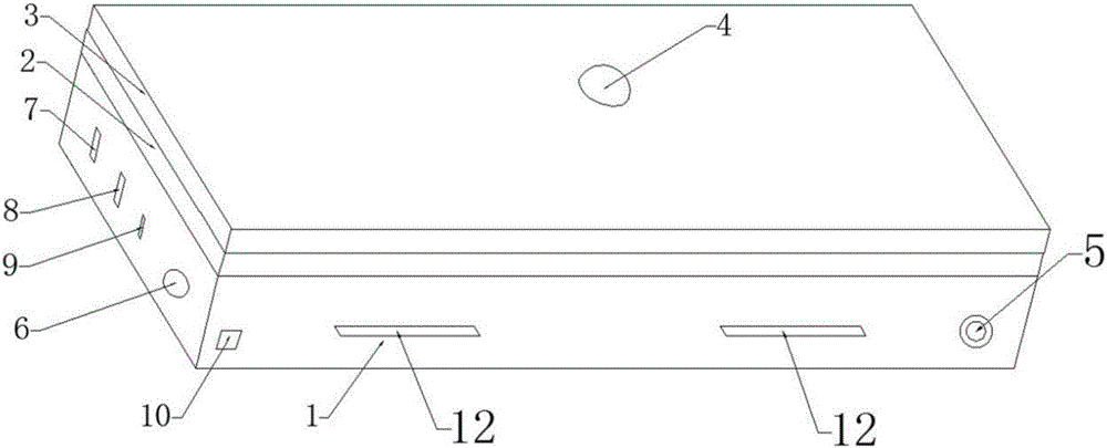
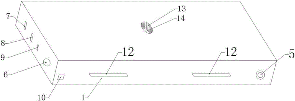
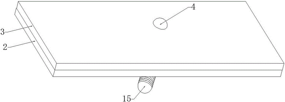
[0035] A new type of mobile power supply, comprising a mobile power supply body 1, a charging port 9 arranged on the mobile power supply body 1, a discharge port a7, a switch 5 and a battery arranged inside the mobile power supply body 1; the side of the mobile power supply body 1 is provided with The first solar cell panel 2, the second solar cell panel 3 and the connecting shaft 4; the middle part of the side of the mobile power supply body 1 is provided with a groove 13; the bottom of the groove 13 is provided with a lower contact 15; the connecting shaft 4 Pass through the first solar cell panel 2 and the second solar cell panel 3 and thread the groove 13, and connect the first solar cell panel 2 and the second solar cell panel 3 to the side of the mobile power supply body 1; the bottom of the connecting shaft 4 An upper contact 14 is provided; the upper contact 14 is in contact with the lower contact 15 to realize the electrical connection between the first solar cell pane...

Embodiment 2

[0037] This embodiment is further optimized based on Embodiment 1. The second solar electrode plate 3 is covered on the first solar electrode plate 2 through the rotating shaft 4, and the second solar electrode plate 3 can take the rotating shaft 4 as the axis, and the first solar electrode plate 3 The surface of the solar electrode plate 3 rotates, so that the second solar battery panel 3 can be rotated by the connecting shaft 4, perpendicular to the first solar battery panel 2, increasing the sun exposure area, and increasing the charging speed of the battery panel as a mobile power supply.

Embodiment 3

[0039] This embodiment is further optimized based on Embodiment 2. A buffer plastic ring 11 is placed around the first solar cell panel 2 to prevent the first solar cell panel 2 and the second solar cell panel 3 from wearing each other.


PUM


Abstract

The invention relates to a power supply and provides a novel power supply. The novel power supply comprises a mobile power supply body, wherein a first solar cell panel, a second solar cell panel and a connecting shaft are arranged on the side face of the mobile power supply body; a groove is formed in the middle part of the side face of the mobile power supply body; a lower contact is arranged at the bottom of the groove; the connecting shaft penetrates through the first solar cell panel and the second solar cell panel and is in threaded connection with the groove; the first solar cell panel and the second solar cell panel are both connected to the side face of the mobile power supply body; an upper contact is arranged at the bottom of the connecting shaft. According to the novel power supply, when no solar cell panel is needed for charging the mobile power supply or the solar cell panel needs to be changed, the first solar cell panel, the second solar cell panel and the connecting shaft can be detached from the mobile power supply body, and people can randomly detach the solar cell panel according to the requirement and favorably maintain and replace the solar cell panel, so that the people can use the novel mobile power supply in a more convenient and economical manner.

Description

technical field [0001] The invention relates to a power supply, in particular to a novel mobile power supply. Background technique [0002] At present, mobile phones have become an essential tool for people to carry with them in their daily work and life, and outdoor mobile phone charging has become a growing headache for people. For this reason, people have invented mobile power supplies, but at present, the battery life of our commonly used mobile power supplies is relatively limited. The largest capacity mobile power bank is about 15000-20000mAh, which is extremely bulky, and it takes about 20 hours to fully charge it. It is not the best choice in terms of safety or portability. Annoyance, and when going out to play or work, there is often no condition to charge the mobile power supply and mobile phone, which affects people's mood and even delays work. [0003] In the prior art, people have designed a solar mobile power supply to enhance the battery life of the mobile po...

Claims


Application Information

Patent Timeline
Patent Type & Authority Applications(China)
IPC IPC(8): H02J7/35
CPCH02J7/35
Inventor 魏霁烁柏雅惠
Owner CHENGDU YANXINGGUO TECH CO LTD
Why Eureka
Try Eureka