Beam bubbler

A bubbler and integrated technology, applied in the field of faucets or showers, can solve the problems of user discomfort, reduced sealing performance, and increased material waste, so as to save installation and maintenance time, ensure sealing performance, and solve labor problems. cost effect

Active Publication Date: 2017-07-14
李军
View PDF3 Cites 8 Cited by
  • Summary
  • Abstract
  • Description
  • Claims
  • Application Information

AI Technical Summary

Problems solved by technology

During the use of this kind of bubbler, although the corresponding effect of foaming can be achieved, the disadvantage is that the water passing through each split hole of the splitter cannot pass through the outermost ring or / and The concentric tubes close to the outermost ring, which causes the water passing through each diversion hole of the outermost ring of the diverter to be directly ejected from the faucet, which causes the water pressure of the water ejected from the outer ring of the faucet to be too large, making the faucet The water pressure of the inner and outer rings of the faucet is unbalanced, especially the water pressure of the water injected from the outer ring of the faucet outlet is greater than the water pressure of the water injected from the inner ring, which can easily cause the injected water to hit the human skin Uncomfortable on the surface, lack of softness, and because of the unbalanced water pressure of the inner and outer rings, it is easy to cause the water ejected from each water hole on the faucet to be deflected, causing the water ejected from the faucet to be scattered, and further In addition, when this product is installed, since the outer wall of the main body is made of hard material, it needs to be sealed with the housing for its installation. At least one sealing groove is arranged on the outer wall of the body, and then a sealing ring is arranged in the sealing groove, or the sealing groove and the sealing ring are installed on the inner cavity wall of the housing. Although this structure solves the sealing problem to a certain extent, However, the manufacturing cost will increase accordingly, and the waste of materials will also increase accordingly. In addition, after a long-term use of the sealing ring, it will be more or less deformed and aged, which will cause a decrease in sealing performance and cause serious damage to the normal use of the product. troubled

Method used


Image

  • Beam bubbler
  • Beam bubbler
  • Beam bubbler

Examples


Embodiment Construction

[0027] Below in conjunction with accompanying drawing, the present invention will be further described with specific embodiment, see figure 1 — Figure 8 :

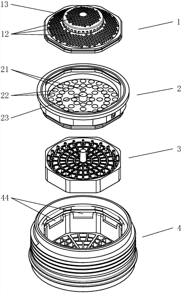
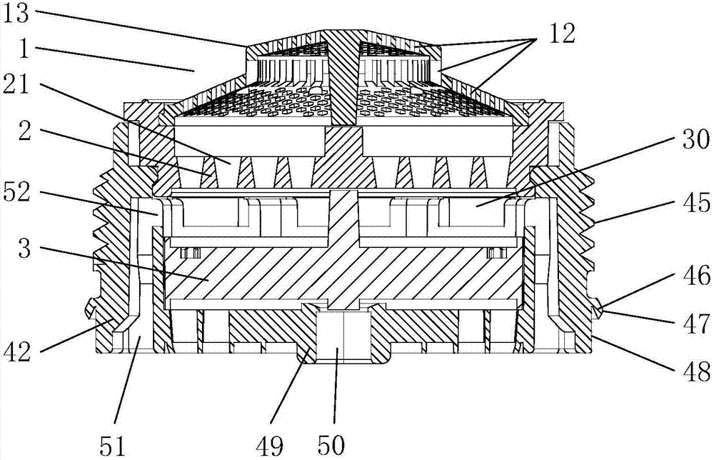
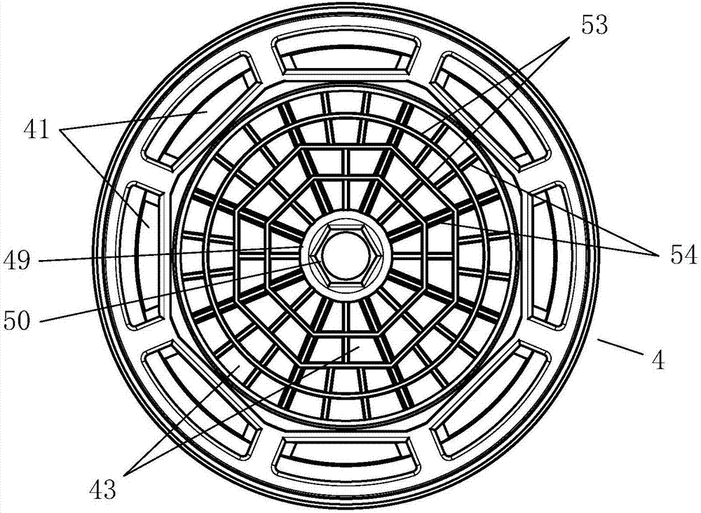
[0028] A jet bubbler, comprising a shell 4 with several water outlet holes 43 arranged on the lower bottom, foaming inserts 3 and rectifiers 2 are arranged at intervals in the shell 4 from bottom to top, and a filter element 1 is connected to the upper end of the rectifier 2 An external thread 45 is integrally formed with the shell 4 on the outer wall 48 of the shell 4 , and an elastic sealing lip 46 is formed integrally with the shell 4 on the outer wall 48 of the shell 4 below the external thread 45 .

[0029] The above-mentioned sealing lip 46 extends outward from the outer wall 48 of the housing 4 and slopes downward to form a cantilever. The outer surface of the cantilever is an arc-shaped sealing surface 47 protruding outward.

[0030] The middle part of the lower bottom of the above-mentioned housing 4 is provide...


PUM


Abstract

The invention belongs to the technical field of faucets or shower heads, and relates to a beam bubbler. The beam bubbler comprises a shell, a plurality of water outlet holes are formed in the lower bottom of the shell; a bubbler plug-in unit and a rectifier are sequentially arranged in the shell from bottom to top at an interval; a filtering part is connected with the upper end of the rectifier; external threads are molded on the outer side wall of the shell in a way of being integrated with the shell; a circle of sealing convex edge having elasticity is molded on the outer side wall, positioned at the lower side of the external threads, of the shell in a way of being integrated with the shell. The beam bubbler has the advantages that the beam bubbler can realize the sealing match during product installation only by means of the self structure without the help of a sealing ring and a sealing groove for matching, thus being good in sealing performance, low in product cost, material-saving, good in beam bubbling effect and high in use comfortableness; therefore, the beam bubbler is suitable for an beam bubbler embedded part arranged at an air outlet of a faucet or a shower head.

Description

technical field [0001] The invention belongs to the technical field of faucets or showers, in particular to a jet bubbler installed on a water outlet of a faucet or a shower. Background technique [0002] The bubbler can fully mix the flowing water and air, so that the water flow has a foaming effect. With the addition of air, the scouring force of the water is greatly improved, thereby effectively reducing water consumption and saving water. At present, the traditional bubbler, such as the "bubbler" disclosed in the Chinese patent literature, is announced as CN205776572U. On the upper side of the device, the splitter is installed on the upper side of the body, and the foaming plug-in is arranged in the body between the splitter and the body; the middle part of the foaming plug-in is provided with a support column, and the support column and the inner side wall of the foaming plug-in There are several concentric tubes with gradually increasing diameters, several reinforcing...

Claims


Application Information

Patent Timeline
Patent Type & Authority Applications(China)
IPC IPC(8): E03C1/084E03C1/086
CPCE03C1/084E03C1/086
Inventor 李军
Owner 李军
Why Eureka
Try Eureka