Eureka AIR delivers breakthrough ideas for toughest innovation challenges, trusted by R&D personnel around the world.

Fiber spreading device

A driving device and vibrating rod technology, applied in textiles and papermaking, etc., can solve the problems of slow winding and unadjustable wrap angle, and achieve the effect of fast threading and easy adjustment.

Active Publication Date: 2020-02-28
NEWTRY COMPOSITE
View PDF5 Cites 1 Cited by
  • Summary
  • Abstract
  • Description
  • Claims
  • Application Information

AI Technical Summary

Problems solved by technology

[0006] In view of this, the present invention proposes a fiber spreading device, which aims to solve the technical problems of slow winding and non-adjustable wrap angle in the prior art when carbon fiber yarn is spread.

Method used


Image

  • Fiber spreading device
  • Fiber spreading device
  • Fiber spreading device

Examples


Embodiment Construction

[0036] Exemplary embodiments of the present disclosure will be described in more detail below with reference to the accompanying drawings. Although exemplary embodiments of the present disclosure are shown in the drawings, it should be understood that the present disclosure may be embodied in various forms and should not be limited by the embodiments set forth herein. Rather, these embodiments are provided for more thorough understanding of the present disclosure and to fully convey the scope of the present disclosure to those skilled in the art. It should be noted that, in the case of no conflict, the embodiments of the present invention and the features in the embodiments can be combined with each other. The present invention will be described in detail below with reference to the accompanying drawings and examples.

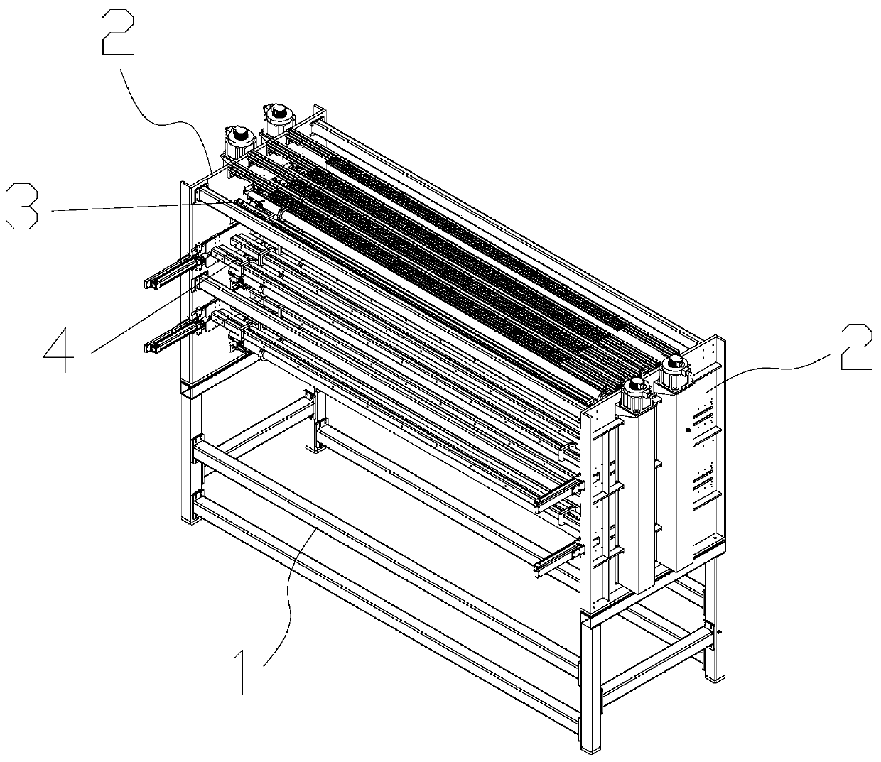
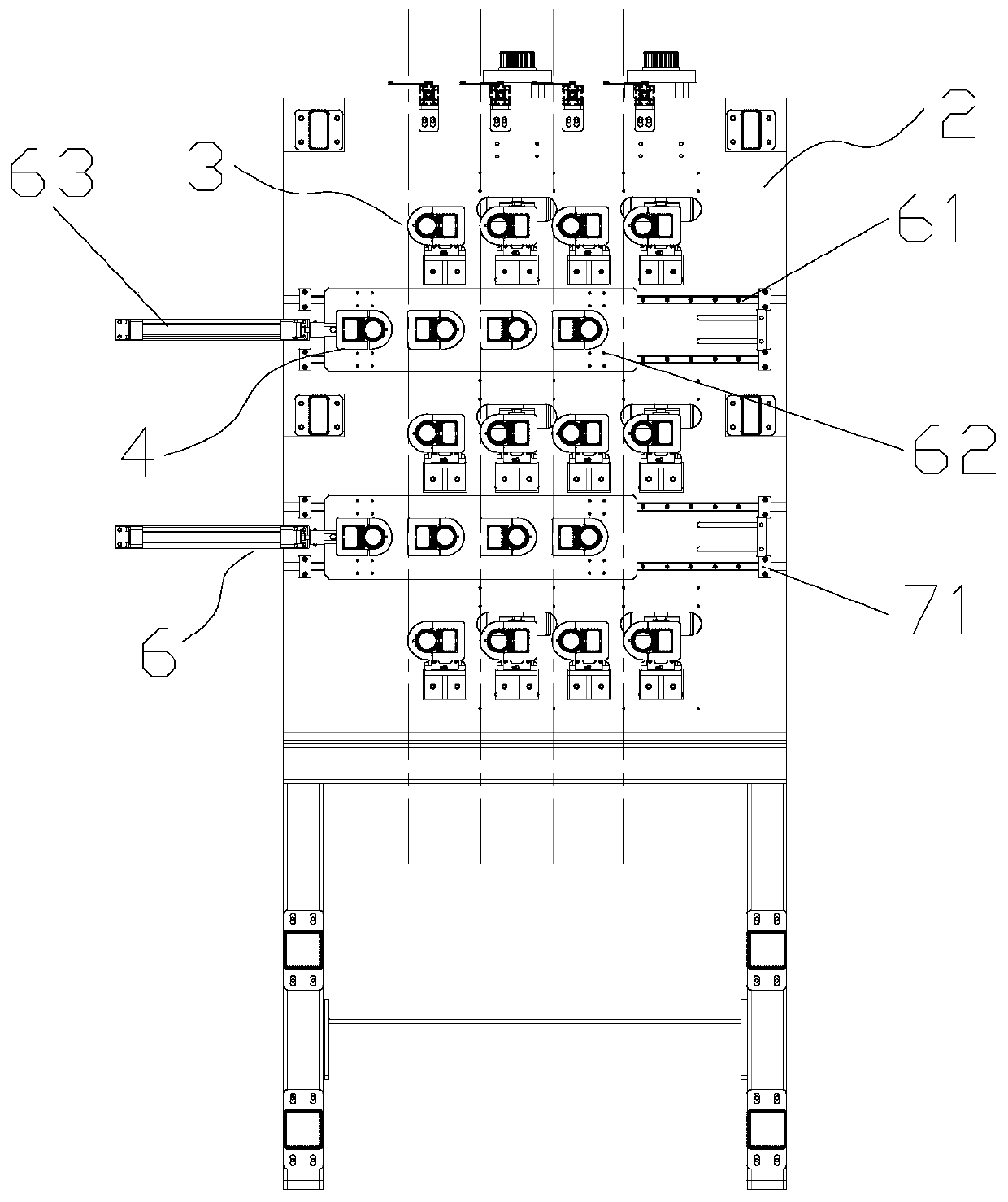
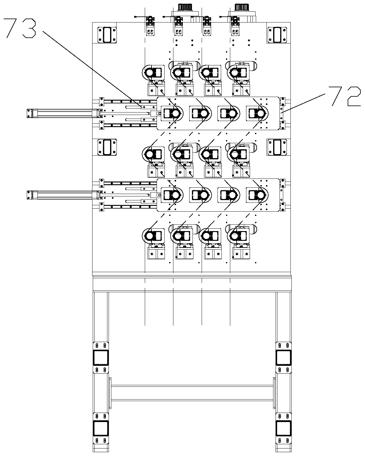
[0037] refer to Figure 1 to Figure 7 , it can be seen from the figure that the fiber spreading device proposed by the embodiment of the present invention in...


PUM


Abstract

The invention provides a fiber spreading device which comprises a supporting frame, two base plates, vibrating rod groups and heating rod groups. The two base plates are oppositely and fixedly connected onto the supporting frame, the vibrating rod groups and the heating rod groups are alternately arranged between the two base plates, the vibrating rod groups reciprocate along the thickness direction of the base plates through a first driving device, and the heating rod groups horizontally slide along the length direction of the base plates through a second driving device. Compared with the prior art, the fiber spreading device has the advantages that the heating rod groups horizontally sliding along the length direction of the base plates can move to the left side when threading is needed,so that a second heating rod of each heating rod group is aligned to a first vibrating rod of the corresponding vibrating rod group, carbon fiber yarns can be directly threaded to the bottom from top, threading is rapid, mistakes are not easily made, the heating rod groups move to the right side to form S-shaped wrap angles when fiber spreading is needed, the wrap angles in fiber spreading can beadjusted at any time by continuing sliding the heating rod groups, and adjustment is facilitated.

Description

technical field [0001] The invention relates to the technical field of carbon fiber spreading, in particular to a fiber spreading device. Background technique [0002] Due to the good overall performance, flexible design, good tensile performance and tear resistance of carbon fiber multiaxial warp knitted fabrics, especially the reinforcement of the yarn along the thickness direction, the interlayer performance is greatly improved, and the interlayer performance of traditional laminates is overcome. Poor weakness, is widely used in aerospace, wind power, track lightweight construction and other fields. Tests on carbon fiber fabrics have shown that the smaller the mass per unit area, the smaller the deviation of its physical properties and the better the operability of the covering. Therefore, the fiber spreading process plays a vital role in the physical properties of fiber products. [0003] For example, the carbon fiber yarn spreading mechanism disclosed in the patent 201...

Claims


Application Information

Patent Timeline
Patent Type & Authority Applications(China)
IPC IPC(8): D02J1/18D02J13/00
CPCD02J1/18D02J13/00
Inventor 沈蓝江谈源李春惠丁文杰
Owner NEWTRY COMPOSITE
Why Eureka
Eureka Blog
Learn More