An electric spindle pneumatic spindle

A spindle and electric spindle technology, applied in textiles and papermaking, can solve the problems of low degree of automation, inability to synchronize electric and pneumatic yarn pulling functions, etc., to increase energy consumption, save generation time, and reduce airflow resistance.

Active Publication Date: 2018-08-03
ANHUI RIFA TEXTILE MACHINERY
View PDF3 Cites 2 Cited by
  • Summary
  • Abstract
  • Description
  • Claims
  • Application Information

AI Technical Summary

Problems solved by technology

[0006] Aiming at the problems that the existing two-for-one twisting machine spindle has a low degree of automation and the electric and pneumatic yarn leading functions cannot be coordinated synchronously, the present invention provides an electric spindle and pneumatic spindle, which can well combine the motor drive and pneumatic yarn leading of the existing two-for-one twisting machine spindle The function realizes the automatic start and stop and yarn drawing, which meets the development requirements of the automation management of the modern textile workshop

Method used


Image

  • An electric spindle pneumatic spindle
  • An electric spindle pneumatic spindle
  • An electric spindle pneumatic spindle

Examples


Embodiment 1

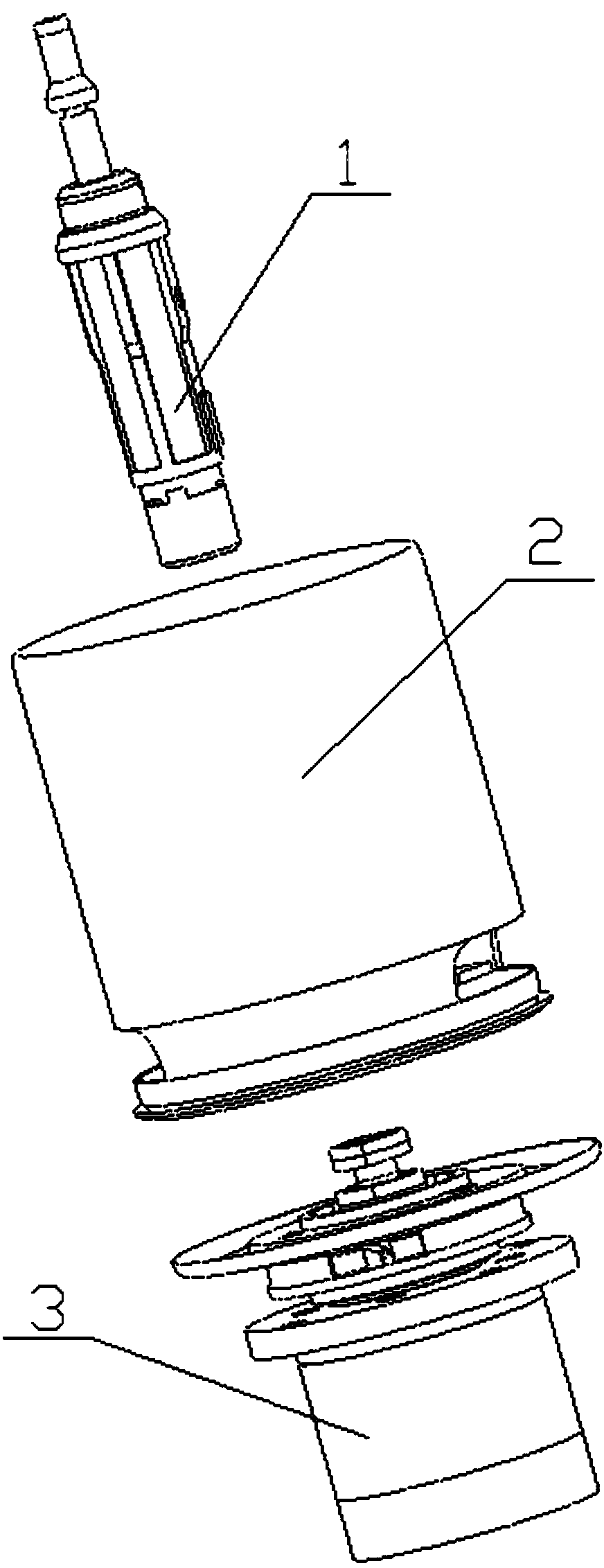
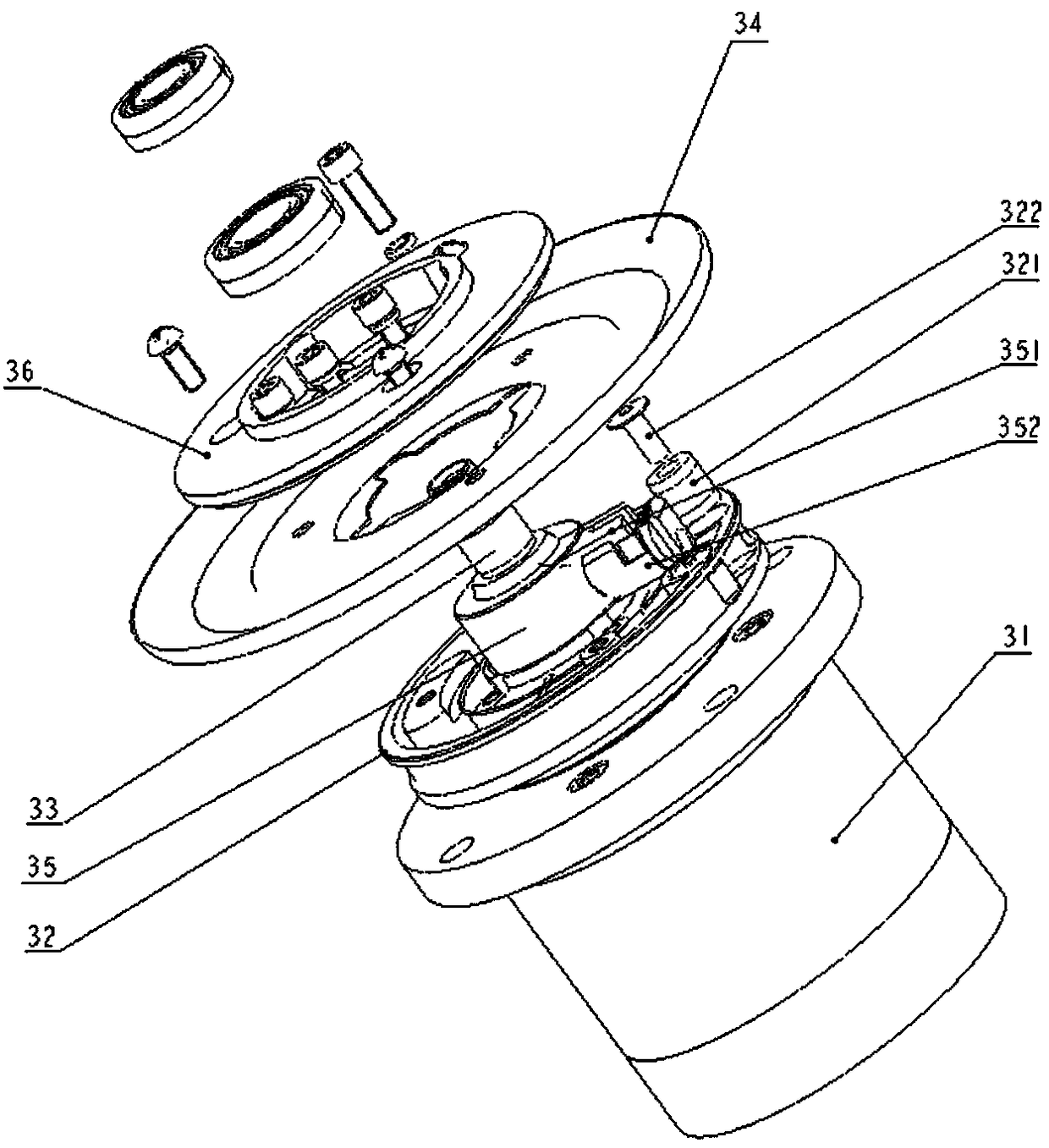
[0045] Such as figure 1 Shown, a kind of electro-spindle pneumatic spindle comprises lining spindle assembly 1, bobbin assembly 2 and rotor assembly 3, and lining spindle assembly 1, bobbin assembly 2 are identical with the component structure in existing common spindle; figure 2As shown, the rotor assembly 3 includes a rotor motor 31, a twisting disk 32, a spindle rod 33, a wire separator disk 34 and a gland 36; Connected, the lower end of the spindle rod 33 passes through the gland 36, the wire separation disc 34, the twisting disc 32 in turn and extends into the rotor motor 31, the spindle rod 33 is relatively fixed with the gland 36, the wire separation disc 34, and the twisting disc 32;

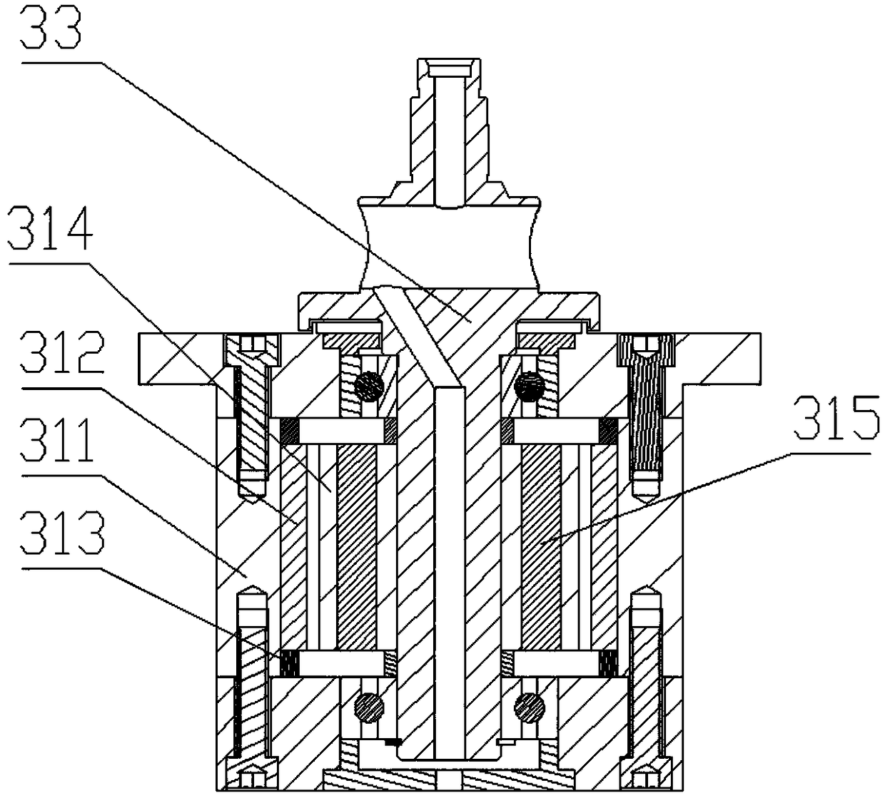
[0046] Such as image 3 As shown, the rotor motor 31 includes a motor casing 311, a stator core 312, a stator winding 313, a rotor core 314 and a permanent magnet 315; On the inner wall, the rotor core 314 is set at the center of the stator core 312; the spindle bar 33 is fixedly conn...

Embodiment 2

[0053] Same as Embodiment 1, the difference is that: in this embodiment, the angle between the air inlet inclined passage 332 and the air inlet straight passage 331 is 60°; 2 directions raise an acute angle with a slope of 3°;

[0054] More importantly: in order to improve the threading effect and improve efficiency, in this embodiment, a silk outlet step groove 356 is also provided at the confluence of the intake horizontal section 354 and the wire inlet bend 355; the wire outlet step groove 356 and the wire outlet channel 323 connection, which increases the volume of the cavity at the confluence of the airflow and increases the negative pressure during the pneumatic yarn threading process, thus enhancing the reliability of automatic yarn threading and improving the efficiency.


PUM


Abstract

The invention discloses an electric pneumatic spindle, belongs to the field of two-for-one twister spindles, and solves the problems of low automation level and no synchronous cooperation of electric and pneumatic yarn guide functions of an existing two-for-one twister spindle. The electric pneumatic spindle comprises a rotor assembly, wherein the rotor assembly comprises a rotor motor and a spindle blade fixedly connected with a rotor iron core on a rotor motor, and further comprises a pneumatic yarn threading device arranged in the spindle blade; the pneumatic yarn threading device comprises a straight air inlet channel, an oblique air inlet channel, a yarn guide cavity, a yarn guide assembly arranged in the yarn guide cavity, and a straight yarn inlet channel; the straight air inlet channel is formed in one end, fixedly connected with the rotor iron core, of the spindle blade; the oblique air inlet channel is connected with the straight air inlet channel; and the straight yarn inlet channel is formed in one end, extending into a yarn pipe assembly, of the spindle blade. According to the electric pneumatic spindle, the motor-driven and pneumatic yarn guide functions of the existing two-for-one twister spindle can be well combined, so that automated start-stop and yarn guiding are realized and the development requirements of automated management of modern spinning and weaving workshops are met.

Description

technical field [0001] The invention belongs to the field of two-for-one twisting machine spindles, and in particular relates to an electric spindle pneumatic spindle. Background technique [0002] The spindle is one of the main components of twisting and winding on the spinning machine, and it is an assembly with a slender rotary shaft supported by two points as the main body. With the development of modern textile technology, the spindle has been driven by a motor. Chinese patent application number 201420388907.5, the patent document published on November 5, 2014, discloses an electric spindle for a two-for-one twister, which belongs to the technical field of textile machinery. The utility model includes a spindle rod, a spindle disk, a base, an installation support mechanism, and a rotor assembly and a stator assembly that cooperate to form a motor. The base is provided with a grooved inner cavity with an opening facing upward, and the rotor assembly and the stator assemb...

Claims


Application Information

Patent Timeline
Patent Type & Authority Patents(China)
IPC IPC(8): D01H7/86D01H7/16
CPCD01H7/16D01H7/86
Inventor 江国勇陈方东
Owner ANHUI RIFA TEXTILE MACHINERY
Why Eureka
Try Eureka