
A central air conditioner with controllable wind direction

A central air-conditioning and wind direction technology, applied in the field of air-conditioning, can solve problems such as long exhaust distance, difficulty in quickly reducing the temperature of air-conditioning, discomfort and illness of personnel, and achieve the effect of protecting indoor personnel and avoiding direct blowing of air-conditioning to the human body

Active Publication Date: 2021-07-20
武汉鑫合悦环境科技有限公司
View PDF7 Cites 0 Cited by
  • Summary
  • Abstract
  • Description
  • Claims
  • Application Information

AI Technical Summary

Problems solved by technology

[0005] Because the air outlet is vertically downward, that is, the angle at which the blades rotate and open is the flow direction of the cold air. However, because the office area is large, and the cooling rate is determined by the air speed and temperature of the cold air, but the central air conditioner has just started, and the temperature of the cold air is difficult. It will drop quickly, so if you want to cool down quickly, you will adjust the wind speed of the central air conditioner to the maximum, so that the cold air will flow out from the air outlet quickly, and the faster the cold air flow, the farther the exhaust distance will be, causing some office workers to directly face the air-conditioning directly. Blowing, a condition that can easily lead to discomfort and illness

Method used


Image

  • A central air conditioner with controllable wind direction
  • A central air conditioner with controllable wind direction
  • A central air conditioner with controllable wind direction

Examples


Embodiment Construction

[0034] The present invention will be described in further detail below in conjunction with the accompanying drawings.

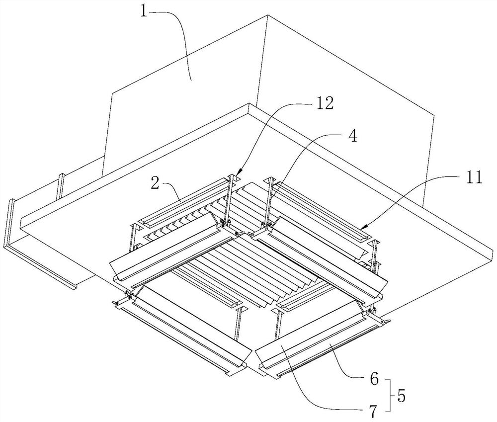
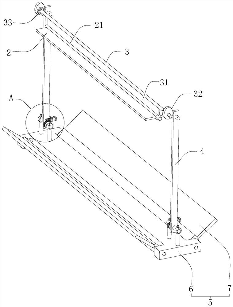
[0035] Such as figure 2 As shown, a central air conditioner with controllable wind direction includes an air outlet fan 1 and a deflector plate 5 arranged below the outlet fan 1. The lower end of the outlet fan 1 is provided with air outlets 11 at intervals in the circumferential direction, and a rotating shaft 21 is arranged in the air outlet 11. And the blade 2, and the lower end of the fan 1 and the two sides in the length direction of the air outlet 11 are connected to the connecting rod 4, the rotation axis of the connecting rod 4 is parallel to the rotation axis of the blade 2, and the lower end of the connecting rod 4 is connected to the drainage The upper end of the plate 5 makes the connecting rod 4 perpendicular to the drainage plate 5;

[0036] When the outlet fan 1 is started, the connecting rod 4 is rotated so that the air guide plate 5 is incl...


PUM


Abstract

The invention relates to a central air conditioner with controllable wind direction, which includes an air outlet fan, the lower end of the air outlet fan is provided with air outlets at equal intervals in the circumferential direction, blades are installed in the air outlet, and the air outlet is arranged at the lower end of the air outlet fan and located The flow control unit below the air outlet. The flow control unit includes a flow guide plate for guiding the cold air to flow upwards and a connecting rod arranged on the top of the flow guide plate. Both ends of the flow guide plate in the length and width direction are provided with connecting rods. The lower end of the fan outlet There are installation grooves on both sides of the length direction of the air outlet, the upper end of the connecting rod is rotatably embedded in the installation groove, and the rotation axis of the connecting rod is parallel to the rotation axis of the blades, and a drive for controlling the rotation of the connecting rod is provided on the fan. unit; by automatically guiding the high-velocity cold air to flow upwards, thereby avoiding the situation where the cold air blows directly on the personnel.

Description

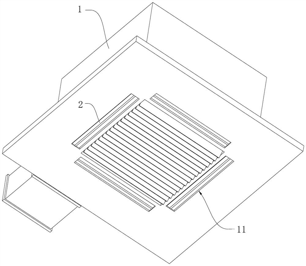
technical field [0001] The invention relates to the technical field of air conditioners, in particular to a central air conditioner with controllable wind direction. Background technique [0002] A central air conditioner is a device used to regulate indoor temperature. [0003] Such as figure 1 As shown, the existing central air conditioner 1 has a square structure, and is often used at the upper end of a large office area. Four air outlets 11 are arranged at equal intervals in the circumferential direction at the lower end of the central air conditioner 1, and blades are installed in the air outlet. 2. When the central air conditioner 1 is started, the blades 2 rotate to open the air outlet 11, and the cold air passes through the air outlet 11 to cool down the room. [0004] There are following defects in the above-mentioned prior art scheme: [0005] Because the air outlet is vertically downward, that is, the angle at which the blades rotate and open is the flow direct...

Claims


Application Information

Patent Timeline
Patent Type & Authority Patents(China)
IPC IPC(8): F24F3/00F24F11/79F24F13/06F24F13/10
CPCF24F3/00F24F13/06F24F13/10F24F11/79
Inventor 姜波黄小芳
Owner 武汉鑫合悦环境科技有限公司
Learn More