Sampling device for soil detection

A sampling device and soil detection technology, applied in the direction of sampling devices, etc., can solve the problems of affecting sampling work, soil sampling at different depths, and easy movement of sampling devices.

Inactive Publication Date: 2020-02-28
陈楠
View PDF0 Cites 17 Cited by
  • Summary
  • Abstract
  • Description
  • Claims
  • Application Information

AI Technical Summary

Problems solved by technology

[0002] The currently used soil sampling devices need to take multiple samples when sampling the soil at different depths, and cannot sample the soil at different depths at one time, which affects the efficiency of soil sampling. At the same time, the existing sampling devices are sampling It is easy to move under the vibration of the process, which will affect the sampling work

Method used


Image

  • Sampling device for soil detection
  • Sampling device for soil detection
  • Sampling device for soil detection

Examples


Embodiment 1

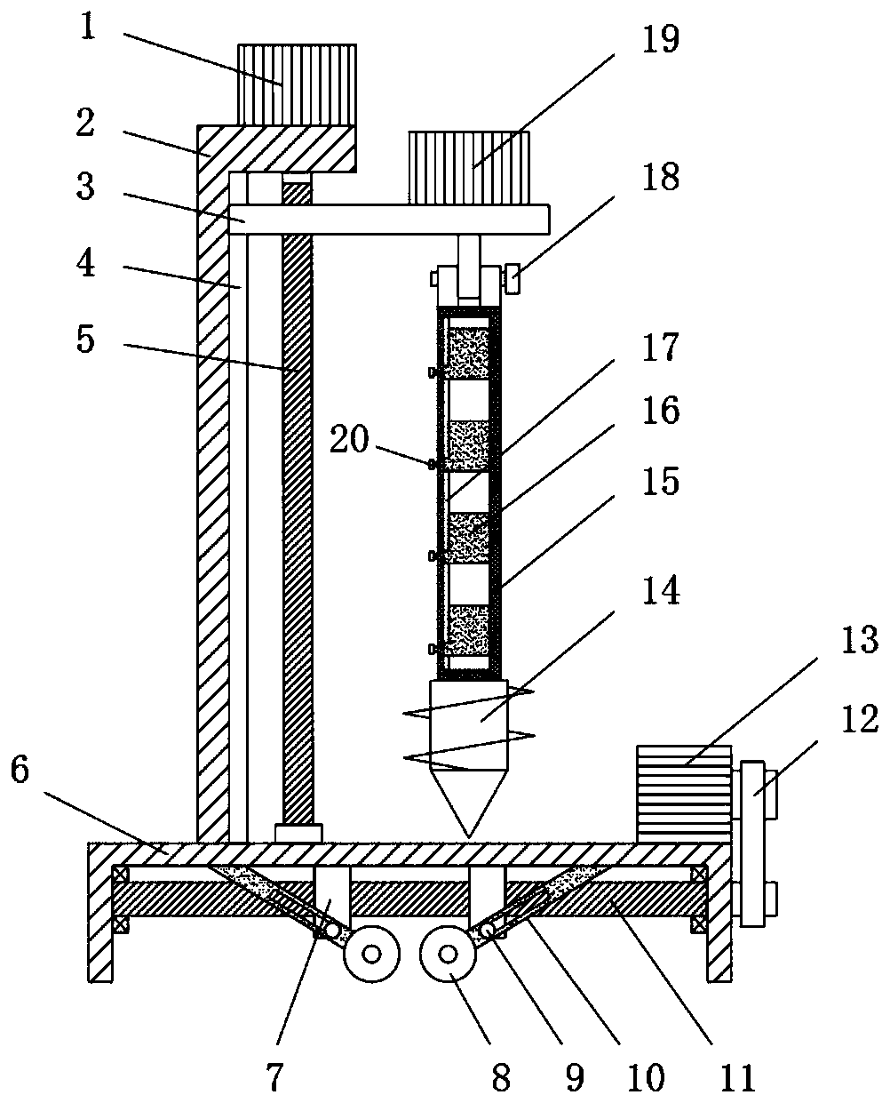
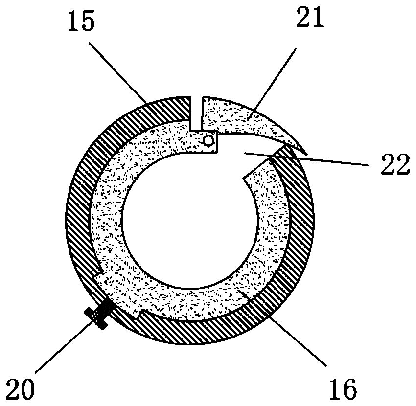
[0023] see Figure 1~4 , in an embodiment of the present invention, a sampling device for soil detection, comprising a base 6 and a soil sampling assembly arranged on the base 6 and a lifting assembly for controlling the lifting of the soil sampling assembly, the soil sampling assembly includes a third drive motor 19 and sleeve 15, the third drive motor 19 is fixedly installed on the lifting assembly, the top of the sleeve 15 is fixedly connected with the output end of the third drive motor 19, the bottom of the sleeve 15 is fixedly equipped with a drill bit 14, the sleeve The inner wall of 15 is provided with a second chute 17, and a plurality of sampling boxes 16 are slided in the second chute 17, and the sampling boxes 16 are fixed between the second bolt 20 and the sleeve 15, and the sleeve 15 And sampling box 16 is all provided with opening 22, and the opening 22 place of sampling box 16 is rotated and is provided with scraper block 21, and described base 6 is also provid...

Embodiment 2

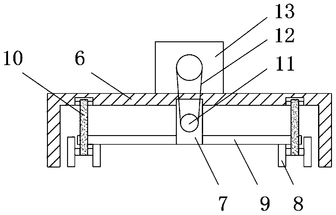
[0030]This embodiment is a further improvement on the basis of embodiment 1. Compared with embodiment 1, the main difference is that: the moving assembly includes a second screw 11 and a swing rod 10, and the second screw 11 is rotatably arranged on the base 6, on the second screw 11, there are two sliders 7 symmetrically sleeved left and right, the two sliders 7 are threadedly matched with the second screw 11 and the threads on the two sliders 7 are reversed, The top of slide block 7 slides and is set on base 6, and the bottom both sides of slide block 7 is fixedly installed with fixed rod 9, and one end of described swing rod 10 is rotatably arranged on base 6, and the other end of swing rod 10 is rotatably provided with The wheel 8 is provided with a bar-shaped groove on the swing rod 10, and the fixed rod 9 is slidingly clamped in the bar-shaped groove of the swing rod 10. The second drive motor 13 is fixedly installed on the base 6, and the second drive motor 13 Through t...


PUM


Abstract

The invention discloses a sampling device for soil detection, which comprises a base seat, a soil sampling component and a lifting component, wherein the soil sampling component and the lifting component are arranged on the base seat; the soil sampling component comprises a third driving motor and a sleeve; a second sliding groove is formed in the inner wall of the sleeve; a plurality of samplingboxes are slidably arranged in the second sliding groove in a clamped manner; the sampling boxes are fixed with the sleeve through second bolts; openings are respectively formed in the sleeve and thesampling boxes; soil scraping blocks are arranged at the openings of the sampling boxes in a rotary manner; and a liftable moving component is further arranged on the base seat. The soil scraping blocks are arranged on the sampling boxes in a rotary manner, so that the soil scraping blocks cling to the sleeve in the process that the third driving motor is forward-rotating the soil, the soil cannotenter into the sampling boxes, and when the third driving motor backward-rotates, the soil scraping blocks can sample soil, so that the purpose of sampling soil with different depths by the device isrealized; and the device is prevented from moving in the sampling process by arranging the liftable moving component.

Description

technical field [0001] The invention relates to a sampling device, in particular to a sampling device for soil testing. Background technique [0002] The currently used soil sampling devices need to take multiple samples when sampling the soil at different depths, and cannot sample the soil at different depths at one time, which affects the efficiency of soil sampling. At the same time, the existing sampling devices are sampling It is easy to move under the vibration of the process, which affects the sampling work. Contents of the invention [0003] The purpose of the present invention is to provide a sampling device for soil testing to solve the problems raised in the above-mentioned background technology. [0004] To achieve the above object, the present invention provides the following technical solutions: [0005] A sampling device for soil detection, comprising a base, a soil sampling assembly arranged on the base, and a lifting assembly for controlling the lifting ...

Claims


Application Information

Patent Timeline
Patent Type & Authority Applications(China)
IPC IPC(8): G01N1/04
CPCG01N1/04
Inventor 陈楠
Owner 陈楠
Why Eureka
Try Eureka