Aerial linker pulling-out tool

A plug-in and aviation technology, which is applied in the field of aviation plug-in extraction tools, can solve the problems of multiple plug-ins, missed extraction, complex surface of aviation parts, etc., and achieve the effect of reducing positioning time, ensuring integrity and avoiding irreversible damage

Inactive Publication Date: 2020-03-06
芜湖市努尔航空信息科技有限公司
View PDF7 Cites 1 Cited by
  • Summary
  • Abstract
  • Description
  • Claims
  • Application Information

AI Technical Summary

Problems solved by technology

[0002] In the field of aircraft manufacturing, due to the more precise cooperation between the internal parts of aviation equipment, and the positioning of more parts with each other, many aviation parts are connected by plugs, but sometimes this kind of plug-in Serious jamming occurs, especially for through-hole aviation parts, the outer surface is more complicated, and there are many plug-ins all over, which is not conducive to inspection and maintenance. Therefore, the development demand of aviation plug-in extraction equipment is greater
[0003] At present, manual extraction is usually used. Some aviation parts have complex surfaces and many curved surfaces. Manual extraction may cause missed extractions. At the same time, the efficiency of manual extraction is low, and the labor cost of extraction is low.

Method used


Image

  • Aerial linker pulling-out tool
  • Aerial linker pulling-out tool
  • Aerial linker pulling-out tool

Examples


Embodiment Construction

[0027] The technical solutions in the embodiments of the present invention will be clearly and completely described below with reference to the accompanying drawings in the embodiments of the present invention. Obviously, the described embodiments are only a part of the embodiments of the present invention, but not all of the embodiments. Based on the embodiments of the present invention, all other embodiments obtained by those of ordinary skill in the art without creative efforts shall fall within the protection scope of the present invention.

[0028] In the description of the present invention, it should be noted that the terms "center", "upper", "lower", "left", "right", "vertical", "horizontal", "inner", "outer", etc. The indicated orientation or positional relationship is based on the orientation or positional relationship shown in the accompanying drawings, which is only for the convenience of describing the present invention and simplifying the description, rather than ...


PUM


Abstract

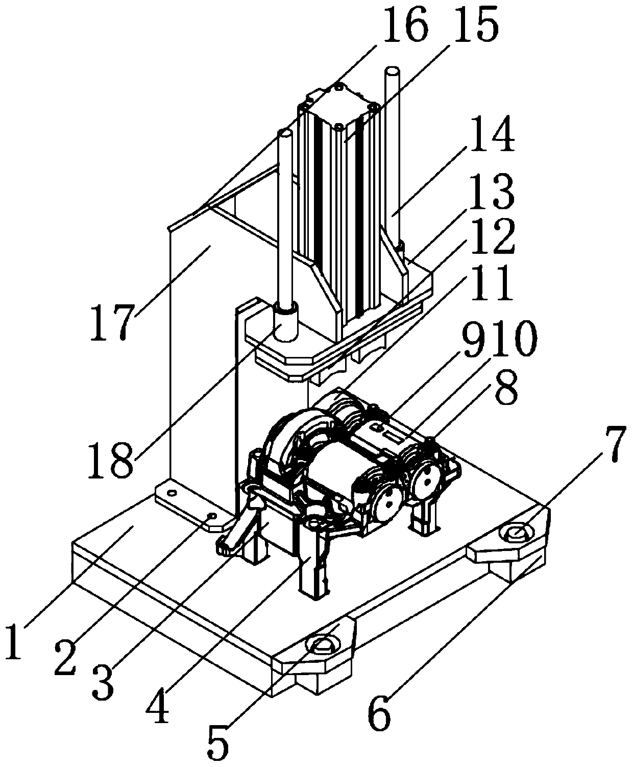
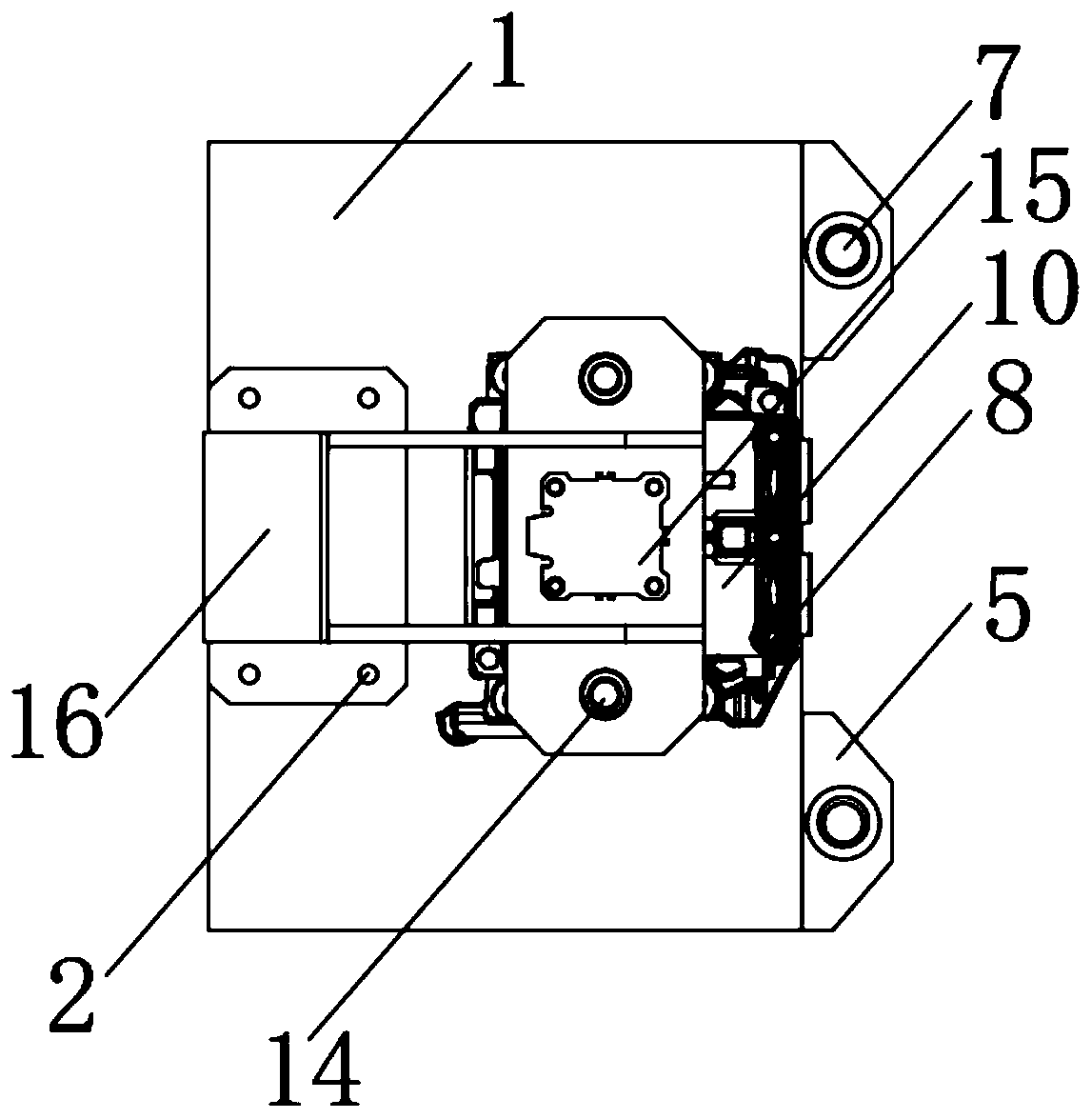
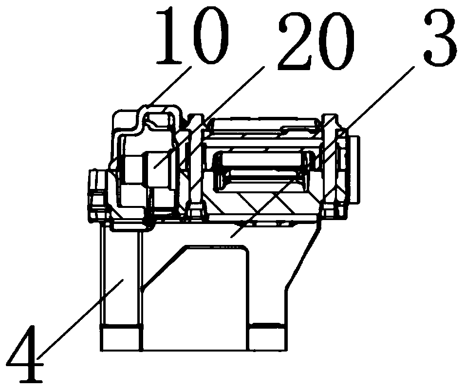
The invention discloses an aerial linker pulling-out tool which comprises a pulling-out worktable. An equipment main supporting plate is perpendicularly arranged on the edge of one side of the pulling-out worktable. A main fixing bolt is formed at the position, close to the surface of the pulling-out worktable, of the equipment main supporting plate. A die main shell is arranged at the middle position of the pulling-out worktable. A conveniently-demounted positioning core is arranged in an inner cavity of the die main shell, and a positioning embedded block is embedded in the surface of the circumference of the top of the die main shell. A die clamping bolt is formed on the surface of the die main shell, and die supporting feet are arranged between the edge of the bottom face of the die main shell and the pulling-out worktable. Die rib plates are arranged at the positions, between the die supporting feet, of the bottom face of the die main shell. A die end cover is connected to the side, close to the conveniently-demounted positioning core, of the die main shell in a bolted manner. According to the aerial linker pulling-out tool, the novel structure is used, an electromagnetic effect is adopted, the pulling-out operation on a magnetic conduction linker in an aerial part is achieved, the positioning time is shortened, and meanwhile irreversible damage to the aerial part of a traditional clamping type pulling-out device is avoided.

Description

technical field [0001] The invention relates to the field of aviation equipment accessories, in particular to a tool for pulling out an aviation plug. Background technique [0002] In the field of aircraft manufacturing, due to the relatively precise cooperation between the internal parts of aviation equipment and the use of more parts to position each other, many aviation parts use a pin-type connection, but this kind of plug-in sometimes Serious jamming occurs, especially for through-hole aviation parts. The outer surface is more complicated, and there are many plug-ins all over the place, which is not conducive to inspection and maintenance. Therefore, there is a greater demand for the development of aviation plug-in extraction equipment. [0003] At present, the hair type is usually pulled out manually. Some aviation parts have complex surfaces and many curved surfaces. Manual pulling out may cause leakage. At the same time, the efficiency of manual pulling out is low, a...

Claims


Application Information

Patent Timeline
Patent Type & Authority Applications(China)
IPC IPC(8): B25B27/02B23P19/02
CPCB23P19/02B25B27/02
Inventor 胡家斌
Owner 芜湖市努尔航空信息科技有限公司
Why Eureka
Try Eureka