Carbon dioxide flooding gas front edge dynamic change prediction method

A technology of dynamic change and carbon dioxide, which is applied in the field of carbon dioxide flooding to enhance oil recovery and gas front dynamic prediction, can solve the problems of large gap between prediction results and actual conditions, high cost of gas tracer testing, heavy workload, etc., to achieve Simple Effects of Data Collection and Processing

Active Publication Date: 2020-03-06
XI'AN PETROLEUM UNIVERSITY
View PDF7 Cites 5 Cited by
  • Summary
  • Abstract
  • Description
  • Claims
  • Application Information

AI Technical Summary

Benefits of technology

Inventors have developed an algorithm that uses measurements from breathing patterns or fluid flow velocity to accurately determine how much oxygen enters tissue during inflammatory processes like blood clotting (blood vessel blockage). By analyzing these measurement values over multiple months' worth of experiments conducted on various types of fluids, they found that there are certain factors affecting the movement of gases within specific areas called chambers where cells die out due to lack of water. These results help researchers better understanding what causes damage caused by excessive levels of nitrogen oxides (NO) emissions.

Problems solved by technology

This patented technical problem addressed in this patents relates to improving the efficiency and effectiveness of capturing C02 emissions through drilling operations (CO2) or injecting water into subterranean formations. Current techniques involve estimating the location of the C02 emission source based solely upon physical measurements such as depths penetrated along boreholes. However, these conventional approaches cannot accurately account for variations caused by factors like temperature fluctuations over time due to environmental conditions. Additionally, existing models used for analyzing fluid movement may provide insights about how certain processes occur within specific locations where they affect the outcome of combustion events.

Method used


Image

  • Carbon dioxide flooding gas front edge dynamic change prediction method
  • Carbon dioxide flooding gas front edge dynamic change prediction method
  • Carbon dioxide flooding gas front edge dynamic change prediction method

Examples


Embodiment Construction

[0050] The present invention will be further described below in conjunction with the accompanying drawings and embodiments.

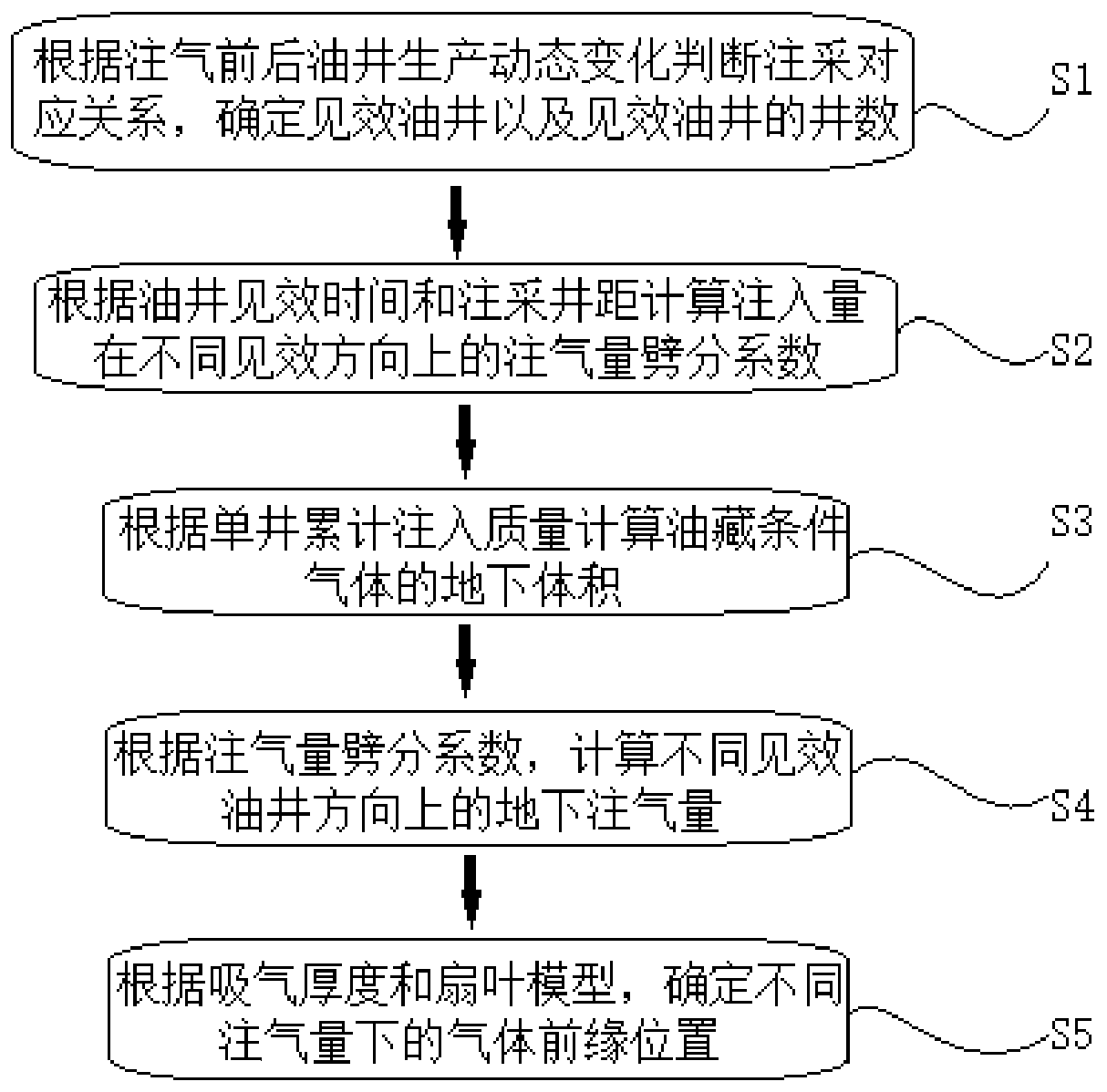
[0051] refer to figure 1 The method for predicting the dynamic change of the carbon dioxide drive gas front of the present invention is a new method for predicting the dynamic change of the gas drive gas front position using the injection-production correspondence relationship of the gas suction profile test, the injection-production well spacing, and the effective judgment of the oil well. It mainly includes five parts: one is to judge the corresponding relationship between injection and production according to the production dynamic changes of oil wells before and after gas injection, and determine the effective oil wells and the number of effective oil wells; The third is to calculate the underground volume of reservoir-conditioned gas based on the cumulative injection quality of a single well; the fourth is to calculate the underground gas injection...


PUM


Abstract

The invention relates to the technical field of carbon dioxide flooding oil recovery increase in oil and gas field development, and discloses a carbon dioxide flooding gas front edge dynamic change prediction method. The carbon dioxide flooding gas front edge dynamic change prediction method includes the following processes that an injection-production corresponding condition is judged by comprehensively considering the suction profile result, the injection-production well spacing and the oil well effective condition, the gas injection volume is split in the different effective oil well directions, the splitting coefficient and the gas injection volume in different oil well directions are calculated according to the gas injection efficiency speed, a fan blade model is used for calculatingthe dynamic change of the gas drive front edge position under different gas injection volumes, and carbon dioxide flooding gas front edge dynamic change prediction is realized. By means of the method,only basic data such as production dynamics data, suction profile data and injection-production well spacing are needed, data collection and processing are simple, through gas drive front edge prediction, the advancement speed of CO2 under the oil deposit condition is better grasped, the gas generating time is better predicted, the dynamic change of the miscible range can be quantitatively calculated in combination with the pressure profile, and a basis is provided for CO2 dynamic tracking evaluation and injection-production parameter optimization adjustment.

Description


Claims


Application Information

Patent Timeline
Owner XI'AN PETROLEUM UNIVERSITY
Why Eureka
Try Eureka