A Traffic Signal Timing Method at the Intersection of Main and Branch Roads

A traffic signal and signal timing technology, which is applied in the direction of traffic signal control, can solve the problems of low traffic efficiency, short cycle time, and inapplicability, so as to improve efficiency and alleviate traffic congestion

Active Publication Date: 2022-01-25
JILIN UNIV
View PDF0 Cites 0 Cited by
  • Summary
  • Abstract
  • Description
  • Claims
  • Application Information

AI Technical Summary

Problems solved by technology

[0004] The purpose of the present invention is to solve the problem that the existing method does not consider the overall traffic flow of the main road and the branch road and the difference in the number of lanes controlled by each phase, resulting in a significantly smaller cycle duration and low traffic efficiency, which cannot be applied in actual engineering problem, and propose a traffic signal timing method at the intersection of main and branch roads

Method used


Image

  • A Traffic Signal Timing Method at the Intersection of Main and Branch Roads
  • A Traffic Signal Timing Method at the Intersection of Main and Branch Roads
  • A Traffic Signal Timing Method at the Intersection of Main and Branch Roads

Examples


specific Embodiment approach 1

[0019] Specific implementation mode one: the concrete process of the traffic signal timing method of a kind of main branch road intersection of this embodiment is:

[0020] Step 1: Obtain the arrival motor vehicle flow of each phase of the intersection;

[0021] Step 2: Transform the arriving motor vehicle flow at each phase of the intersection;

[0022] Step 3: Convert the number of lanes controlled by each phase at the intersection;

[0023] Step 4: Calculate the weight coefficients of each phase of the intersection based on Step 2 and Step 3;

[0024] Step 5: Determine the green light interval time of each phase of the intersection;

[0025] Step 6: Calculate the intersection signal timing parameters; the specific process is:

[0026] Step 61: Calculate the initial cycle duration C of the intersection 0 , the unit is s;

[0027] Step 62: Calculate the green time g of the intersection phase n n , the unit is s;

[0028] Step 63: Calculate the optimal cycle duration C ...

specific Embodiment approach 2

[0030] Specific embodiment two: the difference between this embodiment and specific embodiment one is that the arrival motor vehicle flow of each phase of the intersection is obtained in the step one; the specific process is:

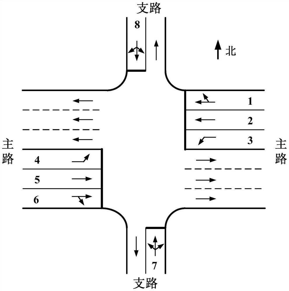
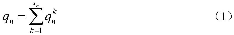
[0031] Investigation and analysis period (such as evening peak 17:00-18:00 or flat peak) the motor vehicle flow of each lane; , Branch roads are regulated, generally the default main road is a road with more lanes and higher road grade, and the branch road is a road with fewer lanes and lower road grade.) There are N phases in total at the intersection, where The number of lanes controlled by phase n is x n , the sum q of the arrival motor vehicle flow of each lane controlled by phase n in the analysis period n ,q n The calculation method is shown in formula (1):

[0032]

[0033] In the formula: is the arrival motor vehicle flow of the kth lane controlled by phase n, the unit is pcu / h; 1≤n≤N.

[0034] Other steps and parameters are the same as...

specific Embodiment approach 3

[0035] Specific embodiment three: the difference between this embodiment and specific embodiment one or two is that in the step two, the arrival motor vehicle flow of each phase of the intersection is converted; the specific process is:

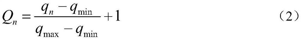
[0036] use Q n Indicates that q n The converted value, Q n The calculation method is shown in formula (2):

[0037]

[0038] In the formula: q max It is the maximum value of motor vehicle flow in each phase, unit: pcu / h; q min It is the minimum value of motor vehicle flow rate arriving at each phase, the unit is pcu / h; 1≤n≤N;

[0039] q max =max(q 1 ,q 2 ,...,q n ,...,q N ) (3)

[0040] q min =min(q 1 ,q 2 ,...,q n ,...,q N ) (4).

[0041] Other steps and parameters are the same as those in Embodiment 1 or Embodiment 2.


PUM


Abstract

The invention relates to a traffic signal timing method at an intersection of main branch roads, and the invention relates to a traffic signal timing method. The purpose of the present invention is to solve the problem that the existing method does not consider the overall traffic flow of the main road and the branch road and the difference in the number of lanes controlled by each phase, resulting in a significantly smaller cycle duration and low traffic efficiency, which cannot be applied in actual engineering question. The process is: 1: Obtain the arriving motor vehicle flow of each phase of the intersection; 2: Transform the arriving motor vehicle flow of each phase of the intersection; 3: Transform the number of lanes controlled by each phase of the intersection; 4: Calculate the intersection The weight coefficient of each phase; Five: Determine the green light interval time of each phase of the intersection; Six: Calculate the signal timing parameters of the intersection; Seven: Generate the signal timing scheme of the intersection. The invention is used in the field of traffic signal timing.

Description

technical field [0001] The invention relates to a traffic signal timing method. Background technique [0002] Traffic signal control intersections where main roads and branch roads intersect are common in urban road networks. The rationality of the signal timing scheme not only affects the operating efficiency of traffic flow on main roads and branch roads, but also affects the traffic flow of surrounding road networks. operating efficiency. In particular, the main road has a large number of lanes and a large traffic flow, which occupies a very important position in the urban road network. How to design the signal timing scheme at the intersection of main and branch roads has been closely watched by traffic managers. [0003] The existing main-branch intersection signal timing method assigns the same weight to the main road and the branch road, and calculates the intersection cycle length and phase green light time according to the traffic flow of the key lane of each phas...

Claims


Application Information

Patent Timeline
Patent Type & Authority Patents(China)
IPC IPC(8): G08G1/08
CPCG08G1/08
Inventor 王琳虹罗禹扬胡宏宇别一鸣季金华郝明杰王贺祺
Owner JILIN UNIV
Why Eureka
Try Eureka