
Chicken house manure cleaning device

A technology for cleaning manure and chicken houses, applied in poultry cages or houses, applications, poultry industry, etc., can solve the problems of serious water consumption, large impact on chicken house environment, poor working environment, etc., to reduce the cost of manure cleaning, The hygienic environment is conducive to improving the effect of breeding income

Inactive Publication Date: 2020-03-17
五莲德瑞达牧业机械有限公司
View PDF5 Cites 7 Cited by
  • Summary
  • Abstract
  • Description
  • Claims
  • Application Information

AI Technical Summary

Problems solved by technology

[0003] During the breeding process, the sanitation of the chicken house has a great impact on the survival of the chicken. At the same time, the health of the chicken house will also affect the health of the workers. Among them, the biggest environmental impact is the chicken manure. Artificial cleaning Manure, not only poor working environment, high intensity, but also increases the cost of breeding, in addition, the existing chicken manure device has poor separation effect, serious water consumption, and great impact on the environment of the chicken house. Based on this, the present invention designs a A kind of chicken coop manure removal device, to solve the above problems

Method used


Image

  • Chicken house manure cleaning device
  • Chicken house manure cleaning device
  • Chicken house manure cleaning device

Examples


Embodiment 1

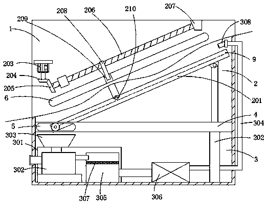
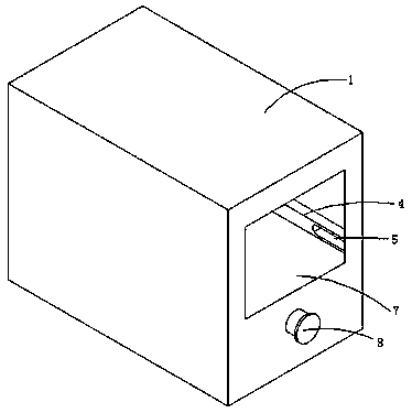
[0021] see Figure 1-2 , the present invention provides a technical solution: a chicken house manure cleaning device, including a chicken cage 1, a cleaning mechanism 2 and a flushing mechanism 3, and the cleaning mechanism 2 includes a bottom plate 201, a telescopic rod 202, a servo motor 203, a bevel gear 204, a pair of Bevel gear 205, screw mandrel 206, connection block 207, slide bar 208, connection plate 209 and cleaning roller 210, on the side wall of the inner cavity of chicken coop 1, be fixedly connected with side plate 4, the left side of side plate 4 is provided with sliding plate. Slot 5, telescopic rod 202 is fixedly connected to the bottom of the inner cavity of the chicken cage 1, one end of the bottom plate 201 is slidably connected to the chute 5 through a rotating shaft, and the other end is hinged on the top of the telescopic rod 202, and the servo motor 203 is fixedly connected to the chicken cage 1, the bevel gear 204 is installed on the output end of the ...

Embodiment 2

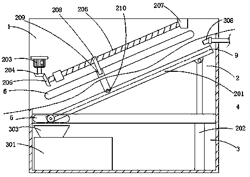
[0030] refer to image 3 Shown, embodiment 2 is different from embodiment 1 in that:

[0031] The nozzle 308 is supplied with water through an external water source, which can maintain the maximization of the manure cleaning intensity, and is suitable for situations where there is a lot of accumulation of chicken manure.


PUM

PropertyMeasurementUnit
Rotation angleaaaaaaaaaa
Rotatable angleaaaaaaaaaa

Abstract

The invention provides a chicken house manure cleaning device and relates to the field of poultry breeding equipment. The chicken house manure cleaning device comprises a chicken cage, a cleaning mechanism and a flushing mechanism, an extensible rod is fixedly connected at the bottom of an inner cavity of the chicken cage, one end of a bottom plate is slidably connected on a sliding groove througha rotating shaft while the other end of the same is hinged at the top of the extensible rod, a through groove is formed in the chicken cage, two connection blocks are positioned above the through groove, a screw rod is rotatably connected between the connection blocks, a sliding rod is connected on the screw rod in a threaded manner, and a cleaning roller is rotatably connected between connectionplates. Through the cleaning mechanism, angle of a bottom plate is adjusted to enable the bottom plate to incline, and the cleaning roller driven by the screw rod on the outer side is also utilized to repeatedly clean the bottom plate; through the flushing mechanism, water is provided cyclically for flushing to clean the bottom plate more thoroughly, in this way, sanitary environment of a chickenhouse is enabled to be conducive to growth of chickens, manure cleaning cost is lowered, and breeding benefit is increased.

Description

technical field [0001] The invention relates to the field of poultry breeding equipment, in particular to a device for removing manure from a chicken house. Background technique [0002] Traditional family chicken coops are simple in structure. Industrialized chicken farming facilities that appeared in the late 1950s not only have environmental conditions suitable for chicken growth and development, but also meet the requirements of mechanization, scientific management, and sanitation and epidemic prevention. With the development of breeding technology , Modern chicken coops also tend to be perfect in castings. [0003] During the breeding process, the sanitation of the chicken house has a great impact on the survival of the chicken. At the same time, the health of the chicken house will also affect the health of the workers. Among them, the biggest environmental impact is the chicken manure. Artificial cleaning Manure, not only poor working environment, high intensity, but...

Claims


Application Information

Patent Timeline
IPC IPC(8): A01K31/04
CPCA01K31/04
Inventor 韩瑞平郑泽冈梁永港于善刚
Owner 五莲德瑞达牧业机械有限公司
Learn More