Injection structure of polymer molding mold

A technology for forming molds and polymers, which can be applied to home appliances, other home appliances, and household components. It can solve the problems of seepage of raw materials, difficulty in processing, and difficulty in ensuring tightness between piercing holes, so as to reduce the amount of waste and reduce seepage. Effect

Active Publication Date: 2021-11-16
KING STEEL MACHINERY
View PDF7 Cites 0 Cited by
  • Summary
  • Abstract
  • Description
  • Claims
  • Application Information

AI Technical Summary

Problems solved by technology

[0004] In the multi-layer mold disclosed by a plurality of mold sheets stacked together in the Chinese Taiwan No. M485818 patent, mold chambers of appropriate shape are usually defined between adjacent mold sheets. Therefore, in order to make the upper supply The raw material can flow down into the lowermost mold chamber space. In the known technology, perforations are respectively provided on each die, and the perforations on each die are aligned coaxially with other preset perforations when the mold is closed. In series, it becomes a flow channel for the raw material to flow down into the mold chamber space; although this technology has been widely used in polymer molding processing technology, but because it divides the single flow channel On different dies, in addition to causing difficulty in processing, it is also difficult to ensure the tightness between the butt perforations when different dies are stacked, so it is easy to produce seepage of raw materials. Obviously, this known technology has not yet reached Complete

Method used


Image

  • Injection structure of polymer molding mold
  • Injection structure of polymer molding mold
  • Injection structure of polymer molding mold

Examples


Embodiment Construction

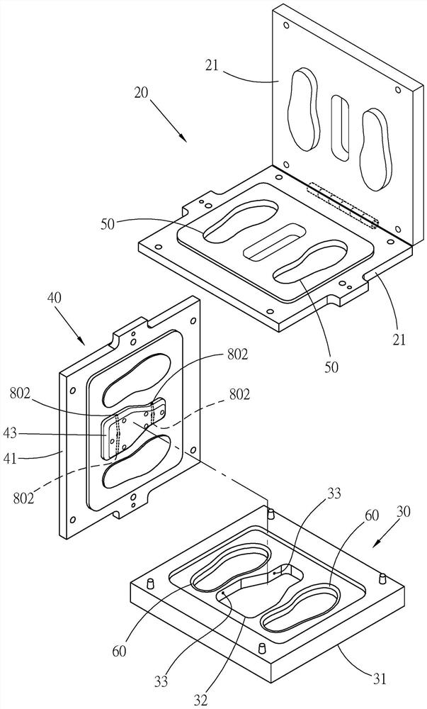
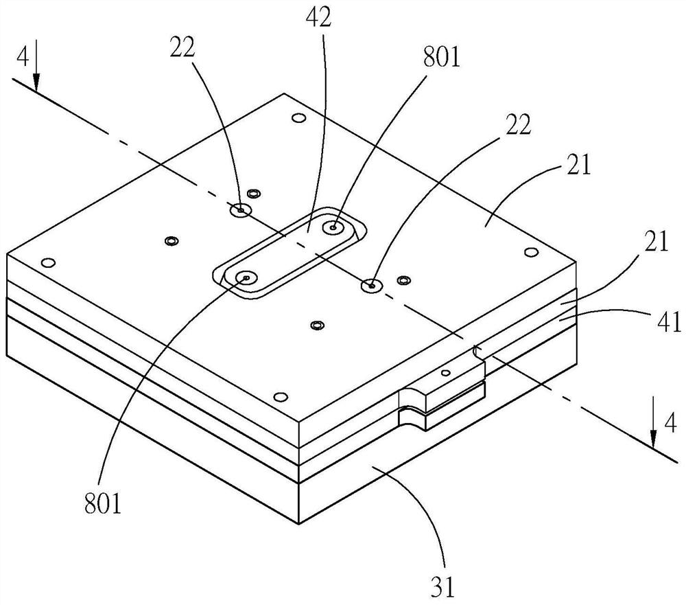
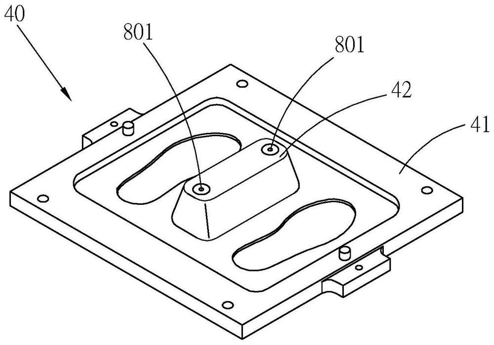
[0033] see Figure 1 to Figure 3 As shown, in a preferred embodiment of the present invention, the injection structure 10 of the polymer article molding mold provided mainly includes a first mold portion 20, a second mold portion 30, and a third mold portion 40. , two mold chambers 50 at the proximal end, two mold chambers 60 at the distal end, a channel 70 and two flow channels 80 .

[0034] First, the prior art in this embodiment will be described in which multiple layers of molds are stacked on top of each other and a mold chamber is formed therebetween. That is, the first mold portion 20 has two plate-shaped first mold bodies pivotally connected to each other. 21; the second mold part 30 has a plate-shaped second mold body 31 with an appropriate thickness, and is located below the first mold part 20; the third mold part 40 has a plate-shaped third mold with an appropriate thickness The body 41 is between the first mold part 20 and the second mold part 30; the proximal mol...


PUM


Abstract

The injection structure of the molding mold for polymer articles provided by the present invention includes a first mold part and a second mold part spaced apart from each other, and a mold part between the first mold part and the second mold part The third mold part, and the supply position of the external raw material is located at the side of the first mold part away from the second mold part, and further, in order to supply the external raw material to the position between the second mold part and the third mold part In the mold chamber of the present invention, the injection structure further includes a passage provided on the first mold part, through which the external raw material can be directly passed through the third mold part from the supply position. The flow channel is injected into the mold chamber, and it is not necessary to make the external raw material flow through the first mold part and the third mold part in sequence before entering the mold chamber as in the known technology, so as to achieve the cost. purpose of the invention.

Description

technical field [0001] The present invention is related to the technology of polymer molding and molding, in particular to a material injection structure of a molding die for polymer articles. Background technique [0002] The mold used in the polymer molding processing technology forms a mold chamber space inside the mold, so that the polymer raw material is molded in the mold chamber to form an item of a specific shape, and among them, the polymer raw material is formed. Filling in the mold chamber, known technologies have disclosed different feeding technologies such as mold opening filler and mold closing injection. The former will open the mold to open the mold chamber, so that the polymer raw material can be directly placed in the open mold chamber. , the latter closes the mold, and when the mold chamber is closed, the flow path for the hot melt polymer raw material is formed through the preset flow channel on the mold, so that the polymer raw material can be passed fr...

Claims


Application Information

Patent Timeline
Patent Type & Authority Patents(China)
IPC IPC(8): B29C45/27B29C45/26B29C45/78B29L31/50
CPCB29C45/2681B29C45/27B29C45/78B29C2945/76531B29L2031/504
Inventor 陈法胜
Owner KING STEEL MACHINERY
Why Eureka
Try Eureka