A material loading system

A material and unloading device technology, applied in the direction of loading/unloading, conveyor objects, transportation and packaging, etc., can solve the problems of low efficiency, large drop height difference, time-consuming, etc., to avoid waste of time, loading and unloading Improve efficiency and reduce environmental pollution

Active Publication Date: 2022-04-08
世邦工业科技集团股份有限公司
View PDF8 Cites 0 Cited by
  • Summary
  • Abstract
  • Description
  • Claims
  • Application Information

AI Technical Summary

Problems solved by technology

[0003] The traditional loading methods include manual loading by loader, belt conveyor loading, and tank loading. Loading by loader requires one shovel after another to move and then load. The efficiency is low, and there is a lot of dust, which wastes manpower and Material resources, high cost
At present, most ores in the mine are transported by belt conveyors, and the ores are transported to the transport vehicles through the belt conveyors. However, the current belt conveyors are mostly fixed structures, and the loading position of the truck needs to be adjusted several times to align the truck with the belt. At the unloading end, it still needs to be adjusted back and forth when unloading, which is very time-consuming, and the height difference of the blanking is large, and the loading dust is large
Loading at the bottom of the tank silo also requires multiple adjustments to the loading position, and the cost of the tank silo is high and the storage capacity is small. To sum up, the existing loading system has low loading efficiency and large environmental dust

Method used


Image

  • A material loading system
  • A material loading system
  • A material loading system

Examples


Embodiment Construction

[0044] In order to make the object, technical solution and advantages of the present invention clearer, the present invention will be described in further detail below in conjunction with specific embodiments and with reference to the accompanying drawings.

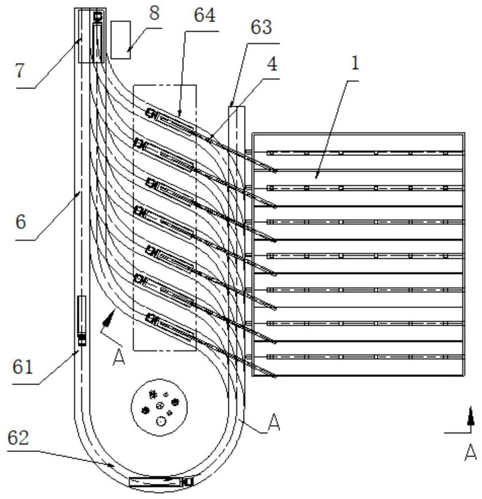
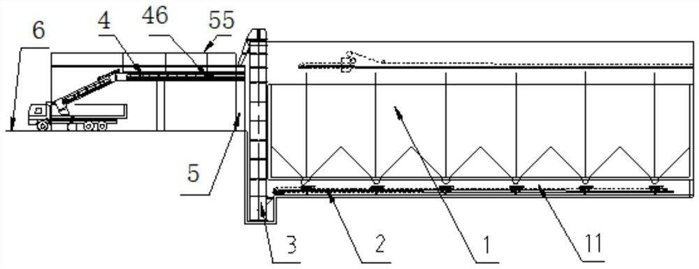
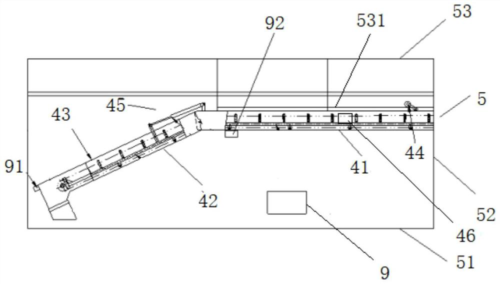
[0045] In one embodiment of the present invention, as Figure 1-3 As shown, a material loading system is provided, including:

[0046] Material warehouse 1;

[0047] The bottom discharge device 2 is connected to the bottom of the warehouse 1, and is used to receive the materials unloaded from the warehouse 1 and output the materials from the bottom of the warehouse 1;

[0048] A lifting device 3 is connected to the front of the warehouse 1, the lifting device 3 includes a bottom feed port and a top discharge port, and the lifting device 3 is used to transfer the material output from the bottom discharge device 2 from the bottom Lift the bottom feed port to the top discharge port;

[0049] Unloading device 4, said unloa...


PUM


Abstract

The invention provides a material loading system, comprising: a material warehouse; a bottom discharge device connected to the bottom of the material warehouse; a lifting device connected to the front of the material warehouse, and the lifting device includes a bottom feeding port and The top discharge port, the lifting device is used to lift the material output by the bottom discharge device from the bottom feed port to the top discharge port; the discharge device, the discharge device includes a feed port and a discharge port The feed port, the feed port of the unloading device is connected to the top discharge port of the lifting device; the unloading device bracket, the unloading device bracket is used to carry the unloading device; the loading path, the loading The road is located in front of the warehouse, and the loading road includes an entrance and an exit, and is used to carry the truck and guide the truck to the discharge port of the unloading device. The invention can greatly improve the flexibility and convenience of unloading operation.

Description

technical field [0001] The invention belongs to the field of material loading, and in particular relates to a material loading system. Background technique [0002] Crushed products are widely used in metallurgy, construction, coal, road construction, chemical and other industries, and play an important role in the industrial production process. According to the product use, they can be divided into different particle sizes, and often need to be loaded and transported multiple times. [0003] The traditional loading methods include manual loading by loader, belt conveyor loading, and tank loading. Loading by loader requires one shovel after another to move and then load. The efficiency is low, and there is a lot of dust, which wastes manpower and Material resources, the cost is higher. At present, most ores in the mine are transported by belt conveyors, and the ores are transported to the transport vehicles through the belt conveyors. However, the current belt conveyors are...

Claims


Application Information

Patent Timeline
Patent Type & Authority Patents(China)
IPC IPC(8): B65G47/51B65G67/08B65G69/18B65G15/26
CPCB65G47/5195B65G67/08B65G69/185B65G15/26B65G2203/0283B65G2203/042
Inventor 杨松科樊碧波
Owner 世邦工业科技集团股份有限公司
Why Eureka
Try Eureka