Flow valve and its position control method and control device

A technology of flow valve and control port, which is applied in the direction of transmission control, fluid pressure actuation device, servo motor components, etc., can solve the problems of system energy waste, hydraulic system out of control, etc., to save energy, improve hydraulic stability, process convenient effect

Active Publication Date: 2022-01-18
UNITED AUTOMOTIVE ELECTRONICS SYST
View PDF6 Cites 0 Cited by
  • Summary
  • Abstract
  • Description
  • Claims
  • Application Information

AI Technical Summary

Problems solved by technology

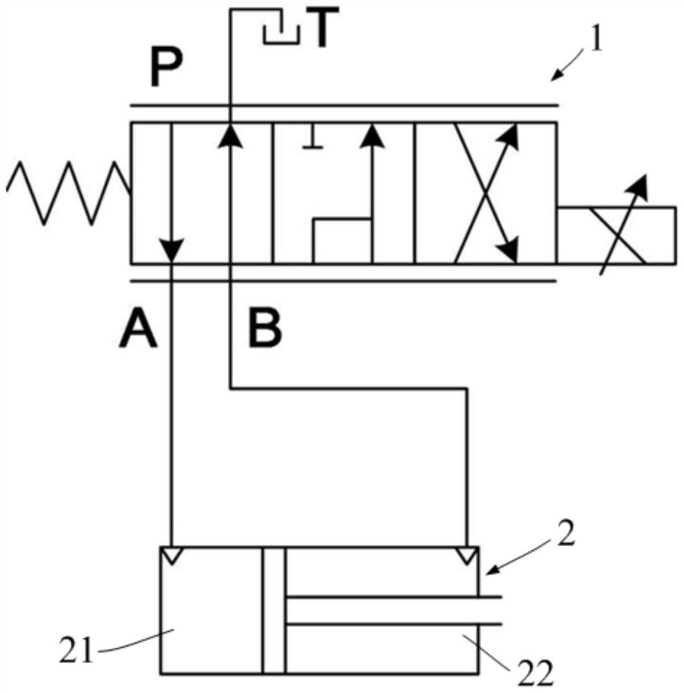
[0004] First, when the control system is unexpectedly powered off, the oil supply port will be connected to one of the control ports to output flow and pressure, causing the hydraulic system to lose control;
[0005] Second, when the double-acting hydraulic cylinder is not used, it is necessary to continuously input a certain amount of current to the flow valve so that the two control ports return oil at the same time, resulting in a waste of system energy

Method used


Image

  • Flow valve and its position control method and control device
  • Flow valve and its position control method and control device
  • Flow valve and its position control method and control device

Examples


Embodiment Construction

[0065] Embodiments of the present invention are described below through specific examples, and those skilled in the art can easily understand other advantages and effects of the present invention from the content disclosed in this specification. The present invention can also be implemented or applied through other different specific implementation modes, and various modifications or changes can be made to the details in this specification based on different viewpoints and applications without departing from the spirit of the present invention. It should be noted that the diagrams provided in this embodiment are only schematically illustrating the basic idea of ​​the present invention, and only the components related to the present invention are shown in the diagrams rather than the number, shape and shape of the components in actual implementation. Dimensional drawing, the type, quantity and proportion of each component can be changed arbitrarily during actual implementation, ...


PUM


Abstract

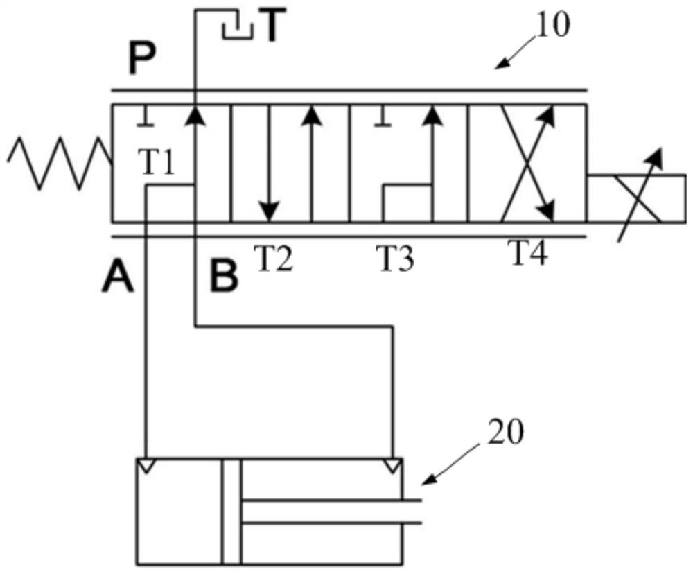
The invention relates to a flow valve and its position control method and control device, which can improve system stability, safety and robustness, and save energy. The flow valve includes a valve sleeve and a valve core. The valve sleeve is provided with first and second oil return ports, oil supply ports, and first and second control ports in sequence. The valve core has first and second functional positions and a first , The second working position. When the flow valve is powered off and the spool is in the first functional position, the two control ports are respectively connected to the corresponding oil return ports, and the oil supply port is not connected to the two control ports; when the flow valve is powered on, the spool moves When it reaches the first working position, the second control port is in communication with the second oil return port, and the oil supply port is in communication with the first control port; The position is the same; when the flow valve is energized to move the spool to the second working position, the first control port is in communication with the first oil return port, and the oil supply port is in communication with the second control port.

Description

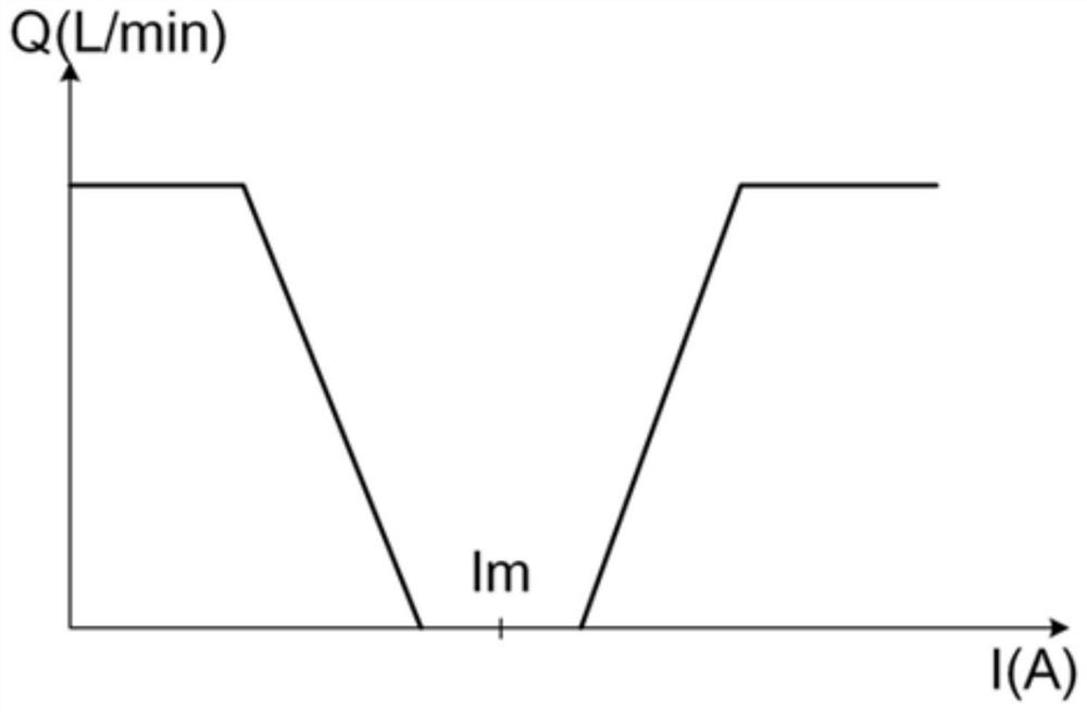
technical field [0001] The invention relates to the technical field of valves, in particular to a flow valve and its position control method and control device. Background technique [0002] The automatic shifting of passenger cars usually adopts the scheme of dual-clutch automatic transmission, and the dual-clutch automatic transmission uses the structure of shift fork and synchronizer to realize the pre-combination of transmission gears. Generally, the position and speed of the shift fork are controlled by a double-acting hydraulic cylinder, and the oil in the two chambers of the double-acting hydraulic cylinder is controlled by a flow valve, so as to realize smooth shifting. [0003] Most of the current flow valves are three-position four-way proportional flow valves (referred to as flow valves), which are equipped with an oil return port, an oil supply port and two control ports. In actual use, the electromagnetic force generated by the electromagnetic force on one side...

Claims


Application Information

Patent Timeline
Patent Type & Authority Patents(China)
IPC IPC(8): F15B13/02F15B13/16F16H61/00
CPCF15B13/021F15B13/16F16H61/0009
Inventor 王磊江明辉文哲孔虎子
Owner UNITED AUTOMOTIVE ELECTRONICS SYST
Why Eureka
Try Eureka