
Depth-fixable soil sampling device

A soil sampling and depth technology, applied in the direction of sampling devices, etc., can solve the problems of inconvenient use, lack of fixed-point sampling function, and inability to sample soil at different depths

Inactive Publication Date: 2020-03-17
陈楠
View PDF0 Cites 1 Cited by
  • Summary
  • Abstract
  • Description
  • Claims
  • Application Information

AI Technical Summary

Problems solved by technology

[0003] Most of the current sampling devices for soil testing do not have fixed-point sampling functions, and cannot sample soil at different depths according to actual needs, which is inconvenient to use

Method used


Image

  • Depth-fixable soil sampling device
  • Depth-fixable soil sampling device
  • Depth-fixable soil sampling device

Examples


Embodiment 1

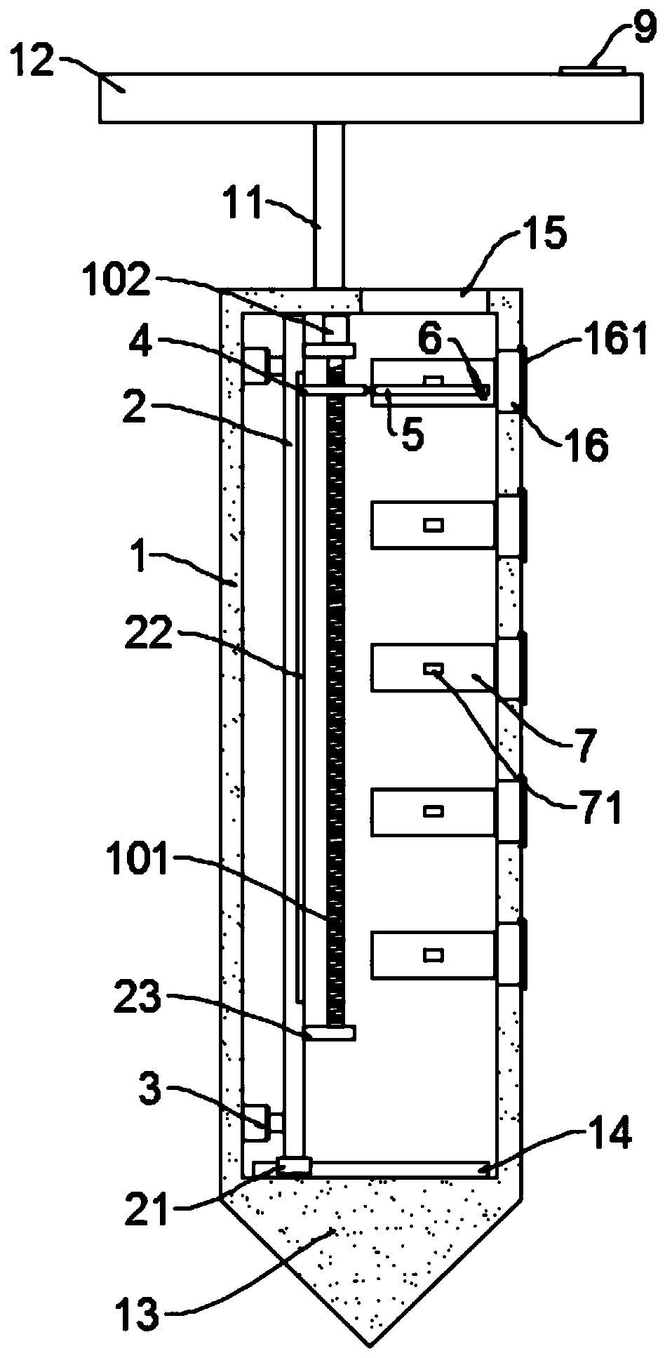
[0023] see Figure 1~4 , in an embodiment of the present invention, a soil sampling device with a fixed depth includes a hollow shell 1, the bottom of the hollow shell 1 is integrally formed with a cone head 12, and the top of the hollow shell 1 is fixed with a connecting rod 11 , the end of the connecting rod 11 is fixed with a pressing handle 12, when in use, by applying force to the pressing handle 12, the hollow casing 11 is pressed into the soil.

[0024] The hollow shell 1 is provided with a moving frame 2, which is slidably connected in the inner cavity of the hollow shell 1 and can move along the horizontal direction, and the hollow shell 1 is provided with a drive moving frame 2 A moving traversing drive mechanism; the moving frame 2 is provided with a chute 22 arranged in the vertical direction, and the sliding card in the chute 22 is provided with a lifting seat 4, and the lifting seat 4 is driven by a lifting drive mechanism; the lifting seat One end of 4 is fixed...

Embodiment 2

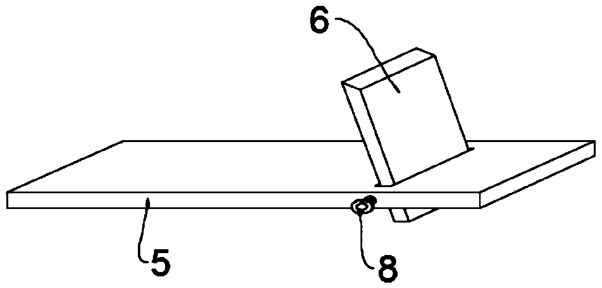
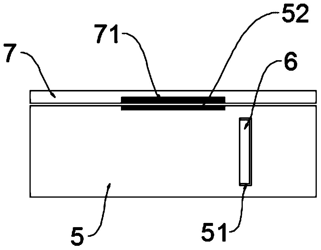
[0034] The difference between this embodiment of the present invention and Embodiment 1 is that an insertion hole 51 is opened on the loading plate 5, and the baffle plate 6 is slidably inserted in the insertion hole 51, and the side edges of the loading plate 5 are connected by threaded fit. There is a locking bolt 8, and the end of the locking bolt 8 extends into the socket 51, so that the baffle plate 6 can be fixed by screwing the locking bolt 8, and the side wall of the hollow shell 1 is provided with an operation The window 17 is used to operate the locking bolt 8 .

[0035] To sum up, in this embodiment, by setting the insertion hole 51 on the material carrier plate 5, the baffle plate 6 is slidably inserted into the insertion hole 51, and with the setting of the locking bolt 8, the baffle plate 6 is relatively The height of the protrusions on the upper surface of the plate 5 can be adjusted. Different heights of the protrusions can allow different amounts of soil to be...


PUM


Abstract

The invention discloses a depth-fixable soil sampling device which comprises a hollow shell. A conical head is integrally formed at the bottom of the hollow shell, a connecting rod is fixed at the topof the hollow shell, and a pressing handle is fixed at the tail end of the connecting rod; a moving frame is arranged in the hollow shell, the moving frame is slidably connected in the inner cavity in the hollow shell and can move in the horizontal direction, and a transverse moving driving mechanism for driving the moving frame to move is arranged in the hollow shell; a sliding groove distributed in the vertical direction is formed in the movable frame, a lifting base is clamped in the sliding groove in a sliding mode, and the lifting base is driven by a lifting driving mechanism; a materialcarrying plate is fixed to one end of the lifting base, and a baffle is arranged on the material carrying plate. The moving frame is arranged in the hollow shell, the lifting base is installed on themoving frame, the material carrying plate is connected with the lifting base, and the transverse moving driving mechanism and the lifting driving mechanism are arranged in a matched mode so that theuser can adjust the sampling depth according to actual requirements and use is more flexible.

Description

technical field [0001] The invention relates to the field of soil detection, in particular to a depth-determinable soil sampling device. Background technique [0002] Soil testing refers to determining the environmental quality (or pollution degree) and its changing trend through the determination of representative values ​​of factors affecting soil environmental quality. What we usually refer to as soil monitoring refers to soil environmental monitoring, which generally includes technical content such as point sampling, sample preparation, analysis methods, result characterization, data statistics, and quality evaluation. [0003] Most of the current sampling devices for soil testing do not have fixed-point sampling functions, and cannot sample soil at different depths according to actual needs, which is inconvenient to use. Contents of the invention [0004] The purpose of the present invention is to provide a depth-determinable soil sampling device to solve the above p...

Claims


Application Information

Patent Timeline
Patent Type & Authority Applications(China)
IPC IPC(8): G01N1/08
CPCG01N1/08
Inventor 陈楠
Owner 陈楠
Learn More