Self-locking supporting device compatible with wiring function

A support device and self-locking technology, applied in the direction of electrical components, etc., can solve problems such as damage to equipment components or display screens, personal injury to operators, and falling down

Pending Publication Date: 2020-03-17
深圳市烽云技术有限公司
View PDF0 Cites 0 Cited by
  • Summary
  • Abstract
  • Description
  • Claims
  • Application Information

AI Technical Summary

Problems solved by technology

[0002] With the diversity of communication equipment, the traditional fixed central computer station or fixed command center can no longer meet the current requirements. At the same time, various types of portable box cover type communication equipment are more and more widely used; (1) Portable box cover For communication equipment, it is often necessary to open the upper cover of the box to operate effectively when preparing for work. According to the application scenarios, commonly used are vehicle-mounted applications, outdoor floor-standing applications, indoor applications, etc. During the working process of the equipment, the upper cover of the box body In the open state, it is easy to fall down under unpredictable external force, resulting in personal injury to the operator or damage to equipment components or display screens. This is a safety and stability issue that has to be considered; (2) at the same time , the box cover type communication equipment is generally divided into two parts, one is the box part, the other is the upper cover part, and the connection between the two is the cable connection

Method used


Image

  • Self-locking supporting device compatible with wiring function
  • Self-locking supporting device compatible with wiring function
  • Self-locking supporting device compatible with wiring function

Examples


Embodiment Construction

[0025] The present invention will be further described below in conjunction with the description of the drawings and specific embodiments.

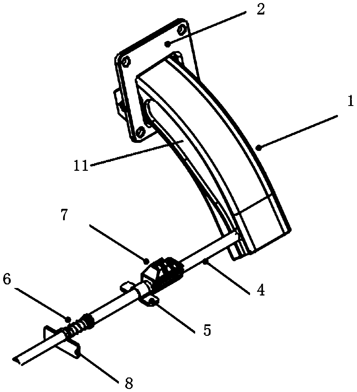
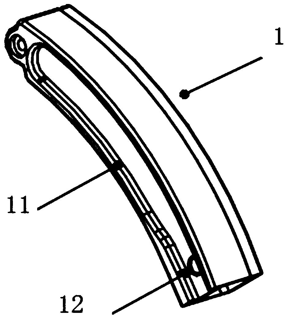
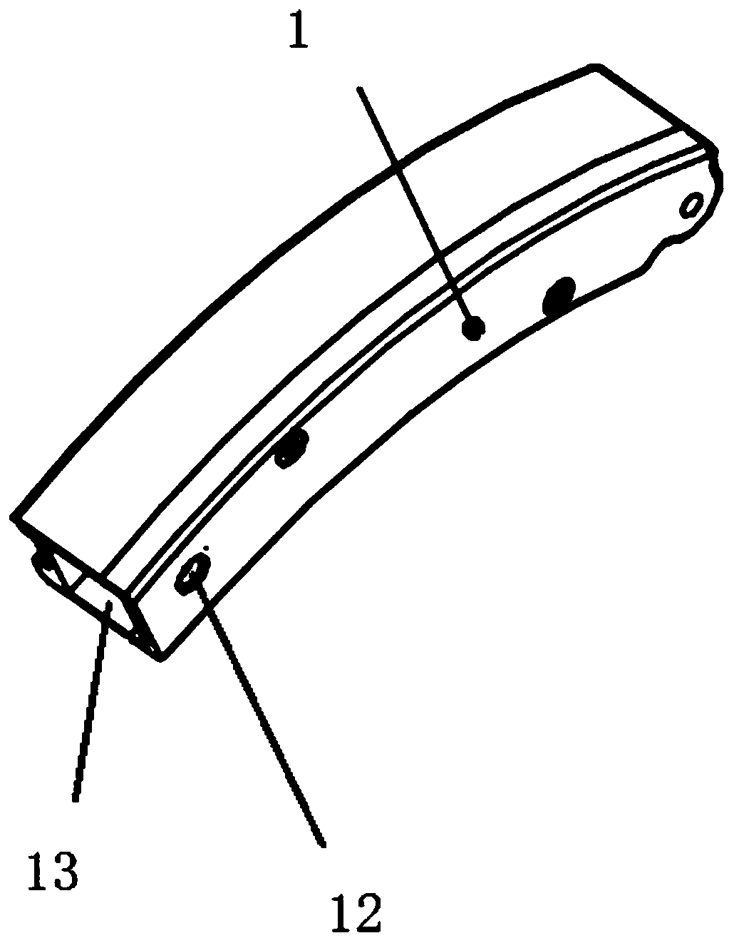
[0026] Such as Figure 1 to Figure 10 As shown, a self-locking support device compatible with the wiring function includes a box cover 9, a box body 10, a connecting body 1 and an elastic self-locking rod mechanism, the box cover 9 and the box body 10 are rotatably connected, and the connecting body 1 is There is a hollow wiring channel 13 running through its upper and lower ends, the upper end of the connecting body 1 is fixedly connected with the box cover 9, the lower end of the connecting body 1 is slidingly fitted with the box body 10, and the box body 10 There is a self-locking hole 101 on the top, the elastic self-locking lever mechanism is set on the box body 10, the connecting body 1 is provided with self-locking lever via holes 12 passing through its two sides, the connecting body 1 The side is provided with a guiding motion tr...


PUM


Abstract

The invention provides a self-locking supporting device compatible with a wiring function. The self-locking supporting device comprises a box cover, a box body, a connecting main body and an elastic self-locking rod mechanism, a hollow wiring channel penetrating through the upper end and the lower end of the connecting main body is arranged on the connecting main body, the upper end of the connecting main body is connected with the box cover, and the upper end and the lower end of the connecting main body are in sliding fit with the box body. A self-locking hole is formed on the box body, andthe elastic self-locking rod mechanism is arranged on the box body. The beneficial effects of the self-locking supporting device are that the self-locking supporting device effectively supports the box cover on the basis of being compatible with the wiring function; on one hand, the safe and firm problem that after the upper cover of a portable box cover type device is opened, the self-locking supporting device topples easily due to touch or topples due to other special conditions, is solved; on the other hand, the problems of partial cable connection, safety and concealment of the upper coverdevice after the upper cover of the portable box cover type device is opened, are solved; and various cables connected to the upper cover of the box body from the lower frame of the box body are protected from being extruded to be broken or twisted.

Description

technical field [0001] The invention relates to portable box cover equipment, in particular to a self-locking support device compatible with cable routing functions. Background technique [0002] With the diversity of communication equipment, the traditional fixed central computer station or fixed command center can no longer meet the current requirements. At the same time, various types of portable box cover type communication equipment are more and more widely used; (1) Portable box cover For communication equipment, it is often necessary to open the upper cover of the box to operate effectively when preparing for work. According to the application scenarios, commonly used are vehicle-mounted applications, outdoor floor-standing applications, indoor applications, etc. During the working process of the equipment, the upper cover of the box body In the open state, it is easy to fall down under unpredictable external force, resulting in personal injury to the operator or dama...

Claims


Application Information

Patent Timeline
Patent Type & Authority Applications(China)
IPC IPC(8): H02G3/08
CPCH02G3/08
Inventor 王坤
Owner 深圳市烽云技术有限公司
Why Eureka
Try Eureka