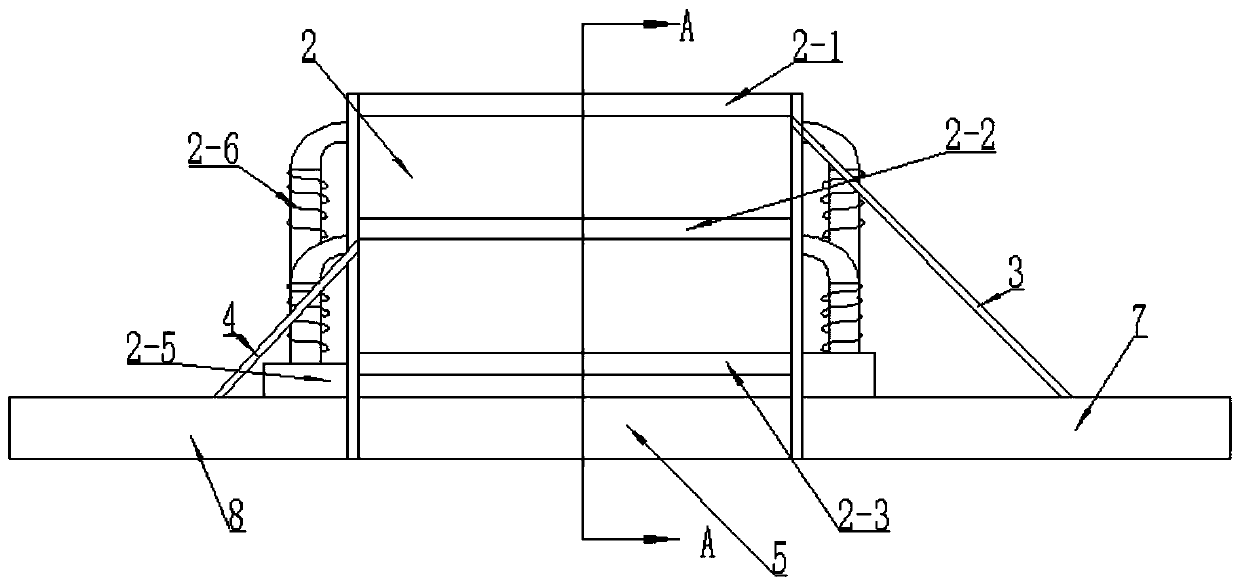
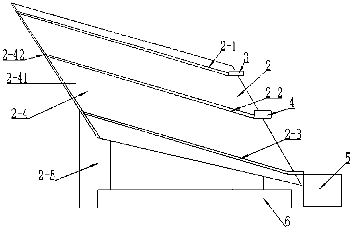
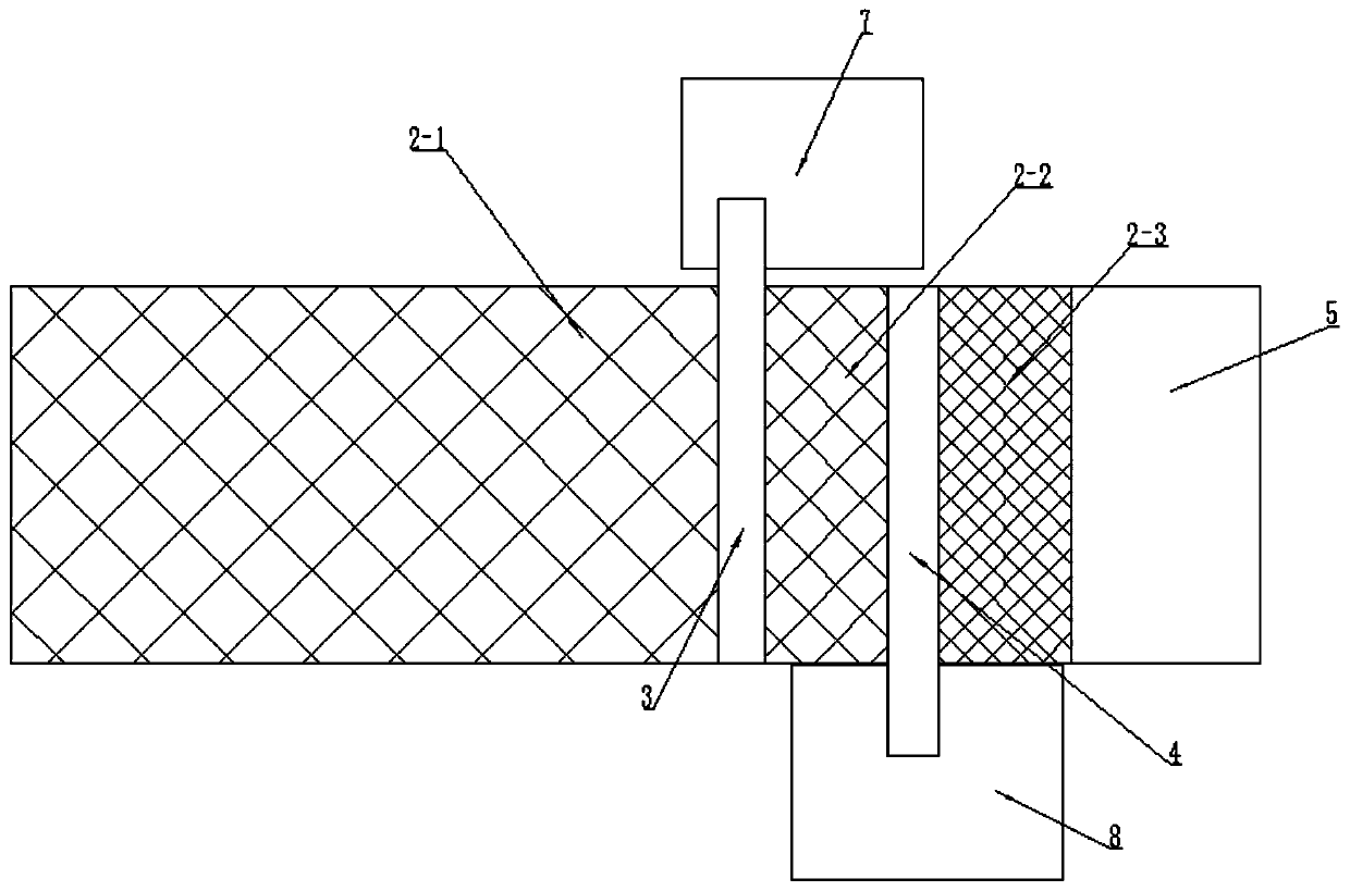
Multistage screening machine for mine powder

A screening machine and powder technology, applied in the field of screening machines, can solve the problems of low degree of dispersion, short travel, incomplete screening, etc., and achieve the effect of increasing screening time and thoroughly screening powder

Pending Publication Date: 2020-03-24
招金矿业股份有限公司蚕庄金矿
View PDF0 Cites 0 Cited by
  • Summary
  • Abstract
  • Description
  • Claims
  • Application Information

AI Technical Summary

Problems solved by technology

[0003] First, the powder falls directly from the lower hopper onto the coarse sieve plate, and the degree of dispersion is not high, resulting in incomplete screening;
[0004] The second is that the powder falls directly from the lower hopper to the middle of the coarse sieve plate, and the upper part of the coarse sieve plate is hardly used, and the distance for the powder to roll down along the coarse sieve plate is short, resulting in incomplete screening;
[0005] The third is that the powder sieved by the coarse sieve continuously falls to the middle sieve, and is distributed along the entire middle sieve. The closer to the lower end of the middle sieve, the shorter the powder travel, and the screening of this part of the powder is not complete; the same reason , the powder sieved from the middle sieve plate is also distributed along the entire fine sieve plate, the closer to the lower end of the fine sieve plate, the shorter the powder travel, resulting in incomplete screening
[0006] In addition, the collecting box of the multi-stage screening machine in the prior art includes a coarse material box, a medium material box, a fine material box and a very fine material box. Only the very fine material box is arranged under the fine sieve plate, and the other three materials The boxes are arranged side by side at the outlets of the three sieve plates, resulting in a large footprint of the entire screening machine

Method used


Image

  • Multistage screening machine for mine powder
  • Multistage screening machine for mine powder
  • Multistage screening machine for mine powder

Examples


Embodiment Construction

[0028] The principles and features of the present invention are described below in conjunction with the accompanying drawings, and the examples given are only used to explain the present invention, and are not intended to limit the scope of the present invention.

[0029] The structures, proportions, sizes, etc. shown in the drawings attached to this specification are only used to match the content disclosed in the specification for the understanding and reading of those who are familiar with this technology, and are not used to limit the conditions for the implementation of the present invention , so it has no technical substantive meaning, and any modification of structure, change of proportional relationship or adjustment of size shall still fall within the scope of the disclosure of the present invention without affecting the functions and objectives of the present invention. within the range covered by the technical content. At the same time, terms such as "front", "rear"...


PUM


Abstract

The invention relates to a multistage screening machine for mine powder. The multistage screening machine for mine powder comprises a screening machine body, the screening machine body comprises a sieve plate mounting frame, a coarse sieve plate, a medium sieve plate, a fine sieve plate and a vibrating mechanism; the sieve plate mounting frame comprises a support and a sieve plate fixing frame; the sieve plate fixing frame comprises side plates and a rear plate; the side plates comprise a left side plate and a right side plate; the rear plate is obliquely arranged, the coarse sieve plate, themedium sieve plate and the fine sieve plate are sequentially arranged from top to bottom, the two sides of the coarse sieve plate, the two sides of the medium sieve plate and the two sides of the finesieve plate are fixed to the left side plate and the right side plate respectively, and the rear ends of the coarse sieve plate, the medium sieve plate and the fine sieve plate are sequentially arranged forwards and fixedly connected with the rear plate; and the vibrating mechanism is mounted on the side plate and can enable the coarse sieve plate, the medium sieve plate and the fine sieve plateto vibrate. The rolling stroke of the powder along the sieve plates is increased, and the screening time of the powder on the sieve plates is prolonged, so that the powder is screened more thoroughly.

Description

technical field [0001] The invention relates to a screening machine, in particular to a multi-stage screening machine for mine powder. Background technique [0002] At present, the existing mine powder multi-stage screening machines generally include upper, middle and lower sieve plates, which are respectively coarse sieve plate, middle sieve plate and fine sieve plate, coarse sieve plate, middle sieve plate and fine sieve plate The apertures of the three sieve plates are all reduced in turn, and the rear ends of the three sieve plates are all aligned. The lower material bin is set above the coarse sieve plate. In the middle of the sieve plate, the powder screening is not complete, the reasons are as follows: [0003] First, the powder falls directly from the lower hopper onto the coarse sieve plate, and the degree of dispersion is not high, resulting in incomplete screening; [0004] The second is that the powder falls directly from the lower hopper to the middle of the c...

Claims


Application Information

Patent Timeline
Patent Type & Authority Applications(China)
IPC IPC(8): B07B1/28B07B1/42B07B1/46
CPCB07B1/28B07B1/42B07B1/46B07B2201/04
Inventor 闫刚姜绍军曹喜青庄晓腾豆娜刘辉杨永杰李涛
Owner 招金矿业股份有限公司蚕庄金矿
Why Eureka
Try Eureka