Linkage braking railway vehicle wheel stopper

A technology for braking rails and wheel stops, which is applied in the direction of brakes interacting between braking elements and rails, railway braking systems, railway car body parts, etc. Insufficient safety factor, staff safety cannot be guaranteed, etc., to achieve the effect of shortening the braking working time, low processing cost, and avoiding direct contact wear

Pending Publication Date: 2020-03-24
CHANGAN UNIV
View PDF0 Cites 5 Cited by
  • Summary
  • Abstract
  • Description
  • Claims
  • Application Information

AI Technical Summary

Problems solved by technology

[0002] Wheel stops are more and more widely used in tunnel projects and rail vehicle braking, but the design of iron shoes has obvious shortcomings in practicability and safety factor
The existing iron shoes on the market have the following defects: First, low safety factor and poor stability. Ordinary iron shoes only rely on the friction between the flat platen and the rail for braking, without side support, poor stability when placed, and require manual labor. Placed at the root of the wheel, the safety of the staff cannot be guaranteed in the event of slippage due to misuse or brake failure; second, the friction is small, and the ordinary iron shoe wheel stopper is made of steel, and the friction between the contact surface with the rail Because steel is in contact with steel, it is easy to generate sparks and the friction force is small. In rainy and snowy weather or in a humid environment, the friction force will be greatly reduced, which will cause the rail vehicle to slip back together with the iron shoes, and cannot play the role of parking brake; The installation and disassembly process of ordinary iron shoes is cumbersome, resulting in unnecessary waste of time and manpower

Method used


Image

  • Linkage braking railway vehicle wheel stopper
  • Linkage braking railway vehicle wheel stopper
  • Linkage braking railway vehicle wheel stopper

Examples


Embodiment Construction

[0024] The present invention will be further described in detail below in conjunction with the accompanying drawings, which are explanations rather than limitations of the present invention.

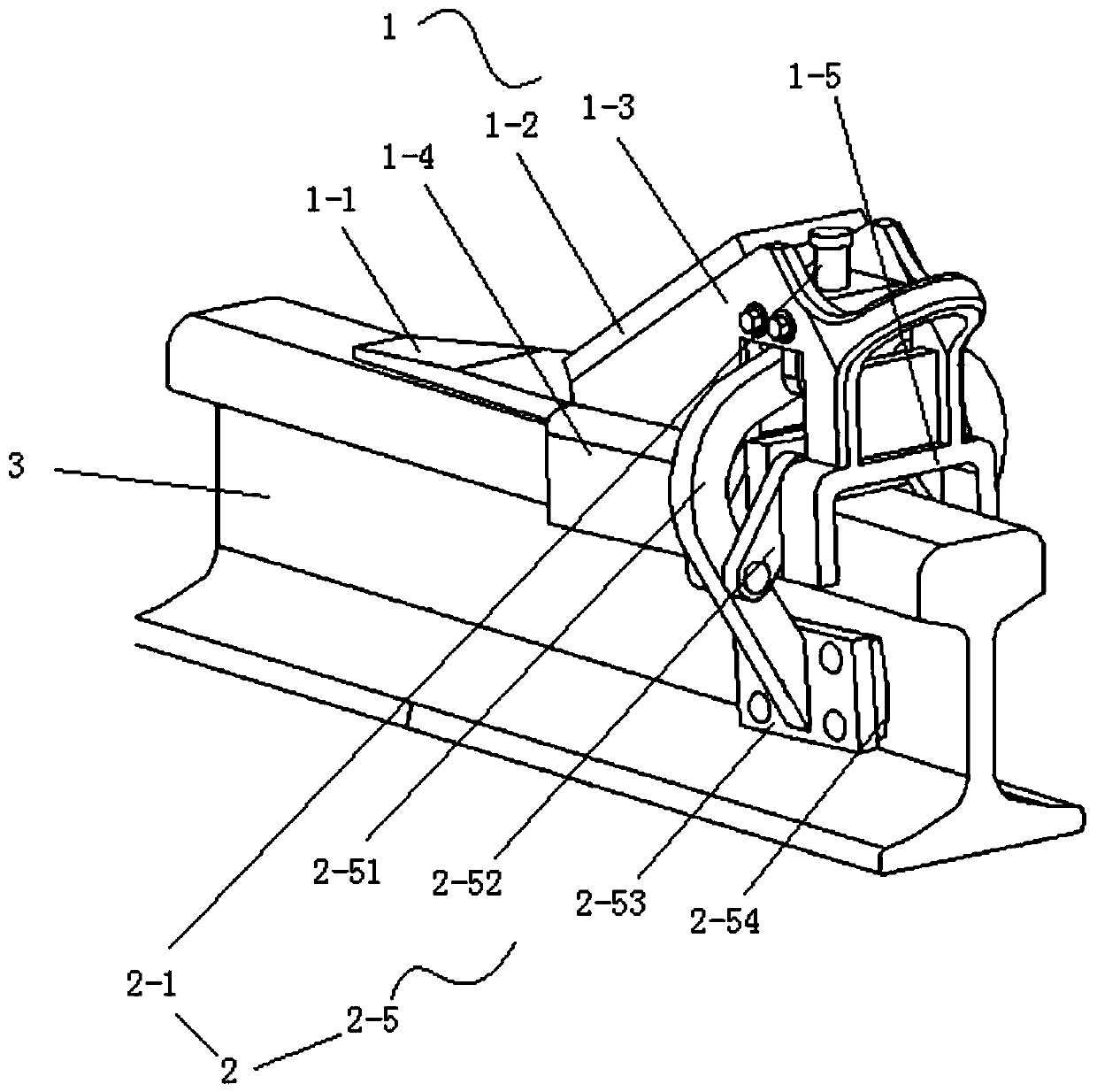
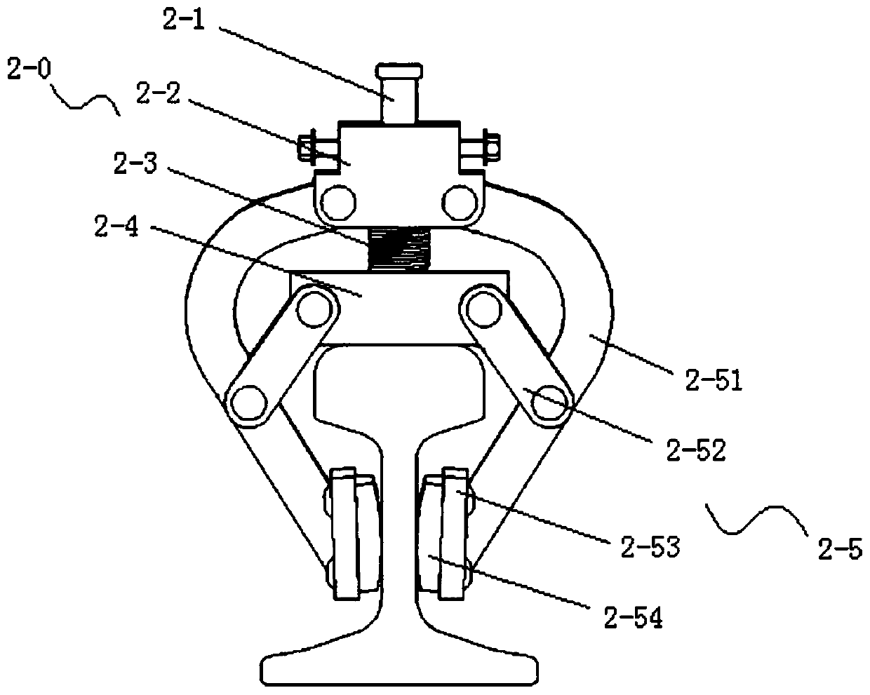
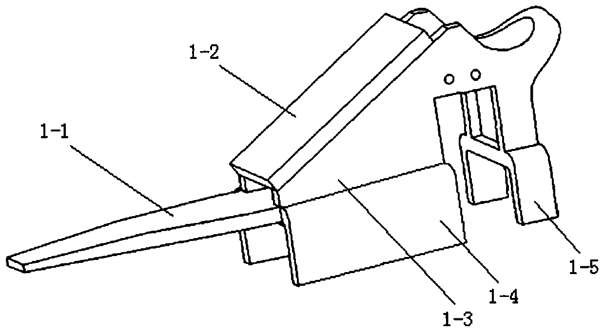
[0025] combine Figure 1-4 , a wheel stopper for a linked brake rail vehicle, comprising a body 1 and a linked brake device 2, the linked brake device 2 is clamped in the body 1, the body 1 is pressed to drive the linked brake device 2 to brake, and the linked brake The device 2 includes a pressure-bearing component 2-0, and the pressure-bearing component 2-0 is linked with a linkage component 2-5; the longitudinal displacement of the pressure-bearing component 2-0 drives the lateral displacement of the linkage component 2-5. When in use, the device is placed on the track 3, the wheels roll and touch and press the device body 1, the body 1 and the upper surface of the track 3 generate friction; the body 1 is pressed to drive the pressure-bearing component 2-0 of the linkage brake device ...


PUM


Abstract

A linkage braking railway vehicle wheel stopper comprises a body and a linkage braking device, the linkage braking device is clamped in the body, the body is pressed to drive the linkage braking device to brake, the linkage braking device comprises a pressure bearing assembly, and the pressure bearing assembly is provided with a linkage assembly in a linkage mode. The pressure-bearing assembly ispressed to move longitudinally to drive the linkage assembly to move transversely. Through the arrangement of the structure, the stability and safety of the wheel stopper are improved, the operation difficulty is reduced, the installation and disinstallation process is simplified, and the working time is shortened.

Description

technical field [0001] The invention belongs to the technical field of wheel stoppers, and in particular relates to a wheel stopper for linked braking rail vehicles. Background technique [0002] Wheel stops are more and more widely used in tunnel projects and rail vehicle braking, but the design of iron shoes has obvious shortcomings in practicability and safety factor. The existing iron shoes on the market have the following defects: First, low safety factor and poor stability. Ordinary iron shoes only rely on the friction between the flat platen and the rail for braking, without side support, poor stability when placed, and require manual labor. Placed at the root of the wheel, the safety of the staff cannot be guaranteed in the event of slippage due to misoperation or brake failure; second, the friction is small, the ordinary iron shoe wheel stopper is made of steel, and the friction with the contact surface of the rail Because steel is in contact with steel, it is easy...

Claims


Application Information

Patent Timeline
Patent Type & Authority Applications(China)
IPC IPC(8): B61H7/12B61H7/02
CPCB61H7/12B61H7/02
Inventor 杨延璞田星穆雪如杨帆张伟峰巩银兵任瑾
Owner CHANGAN UNIV
Why Eureka
Try Eureka