Electric horizontal movement rotary disc trolley

A turntable and electric technology, which is applied to railway car body components, railway braking systems, brakes with pressure braking surfaces, etc., can solve the problem of difficult control of the position of the conveying trolley, failure to meet the use requirements, poor safety performance, etc. The problem is to achieve a good braking effect, reduce the distance to continue moving, and prevent collisions

Active Publication Date: 2017-08-11
YANCHENG CITY LONGQIANG MACHINERY MFG
View PDF5 Cites 2 Cited by
  • Summary
  • Abstract
  • Description
  • Claims
  • Application Information

AI Technical Summary

Problems solved by technology

[0002] In the painting industry, it is often necessary to use a conveying trolley to transport the workpiece to the spray booth. When the existing conveying trolley transports the workpiece to the spray booth, it can only be braked by the brake pad on the drive shaft. If the workpiece on the conveying trolley is heavy , it is difficult to brake the conveying trolley by relying solely on the brake disc on the drive shaft, and the conveying trolley will continue to move for a certain distance under the action of inertia, so it is difficult to control the position of the conveying trolley in the spray booth. Once the control is not good, it will be easy The conveying trolley collides with the spray booth, resulting in damage to the workpiece, poor safety performance, and unable to meet the use requirements

Method used


Image

  • Electric horizontal movement rotary disc trolley
  • Electric horizontal movement rotary disc trolley

Examples


Embodiment Construction

[0009] The specific content of the present invention will be described in detail below in conjunction with the accompanying drawings and specific embodiments.

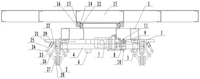
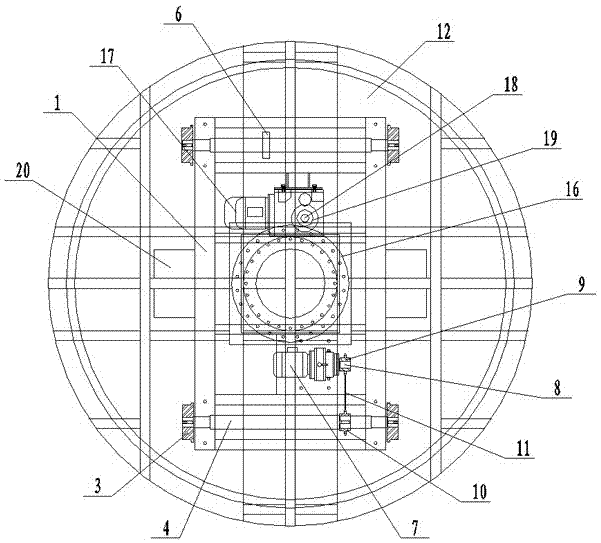
[0010] Such as figure 1 , figure 2 As shown, the electric translation turntable car includes: a vehicle frame 1 and two slide rails 2 arranged on the ground, and a drive shaft 4 is respectively arranged on the front and rear sides of the lower end of the vehicle frame 1 through the rotation of the first bearing seat 3, The two ends of the drive shaft 4 protruding from the first bearing seat 3 are respectively provided with drive rollers 5, and the drive rollers 5 are respectively slidably arranged on the slide rail 2, and a brake disc is provided on the front drive shaft 4. 6. A first servo deceleration motor 7 is provided at the lower end of the vehicle frame 1, a drive sprocket 9 is provided on the motor shaft 8 of the first servo deceleration motor 7, and a driving sprocket 9 is provided on the rear drive shaft 4 ...


PUM


Abstract

The invention discloses an electric horizontal movement rotary disc trolley. The electric horizontal movement rotary disc trolley comprises a frame and two sliding rails arranged on the ground. Driving shafts are rotationally arranged on the front side and the rear side of the lower end of the frame through first bearing blocks correspondingly. The two ends, stretching out of the corresponding first bearing blocks, of each driving shaft are provided with driving wheels. The driving wheels are arranged on the sliding rails in a sliding manner. The driving shaft on the front side is provided with a braking disc. A first servo speed reduction motor is further arranged at the lower end of the frame, and a motor shaft of the first servo speed reduction motor is provided with a driving chain wheel, a driven chain wheel is arranged on the driving shaft on the rear side, and the driving chain wheel is connected with the driven chain wheel through a chain. A pivotal bearing inner ring is arranged at the upper end of the frame, and a pivotal bearing outer ring is rotationally arranged on the rotation bearing inner ring through a rolling body.

Description

technical field [0001] The invention relates to a painting auxiliary equipment, in particular to an electric translation turntable vehicle. Background technique [0002] In the painting industry, it is often necessary to use a conveying trolley to transport the workpiece to the spray booth. When the existing conveying trolley transports the workpiece to the spray booth, it can only be braked by the brake pad on the drive shaft. If the workpiece on the conveying trolley is heavy , it is difficult to brake the conveying trolley by relying solely on the brake disc on the drive shaft, and the conveying trolley will continue to move for a certain distance under the action of inertia, so it is difficult to control the position of the conveying trolley in the spray booth. Once the control is not good, it will be easy The conveying trolley collides with the spray booth, resulting in damage to the workpiece, poor safety performance, and unable to meet the use requirements. Contents...

Claims


Application Information

Patent Timeline
Patent Type & Authority Applications(China)
IPC IPC(8): B05B15/12B61H5/00B61H7/12
CPCB05B16/95B61H5/00B61H7/12
Inventor 王顺山王连华王峰
Owner YANCHENG CITY LONGQIANG MACHINERY MFG
Why Eureka
Try Eureka