Pipe bending device and pipe bending method

A technology of bending device and bending roller, which is applied in the field of pipe bending device and pipe bending, can solve the problems of large-scale and cost-increasing, undisclosed bending processed pipes, and the scheme of applying torsion, etc., and achieves easy operation and maintenance, Realization of miniaturization, simplification, and cost reduction

Active Publication Date: 2014-01-22
SUMITOMO WIRING SYST LTD
View PDF8 Cites 15 Cited by
  • Summary
  • Abstract
  • Description
  • Claims
  • Application Information

AI Technical Summary

Problems solved by technology

[0010] The tube bender proposed in Patent Document 1 inserts the core gold rod 100 into the hollow of the tube to be bent to hold the tube, so there is a problem that it cannot be used when the wire harness is passed through the inside of the tube.
[0011] In addition, in the above-mentioned pipe bender, it is not disclosed that twisting is applied to the pipe being bent, and it is not known whether the pipe can be bent in three-dimensional directions.
[0012] On the other hand, if the above-mentioned manipulator widely used in the past is used, it is complicated, enlarged and costly, and there are problems of difficulty in operation and maintenance.

Method used


Image

  • Pipe bending device and pipe bending method
  • Pipe bending device and pipe bending method
  • Pipe bending device and pipe bending method

Examples


Embodiment Construction

[0056] Hereinafter, embodiments of the present invention will be described with reference to the drawings.

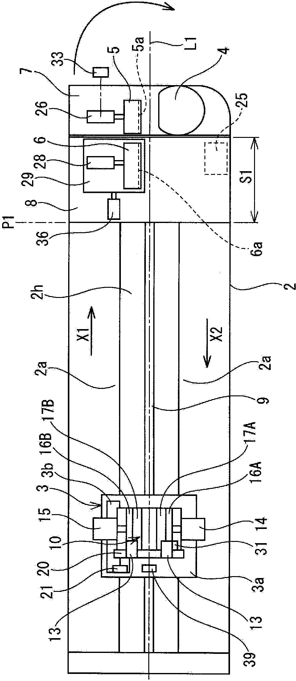
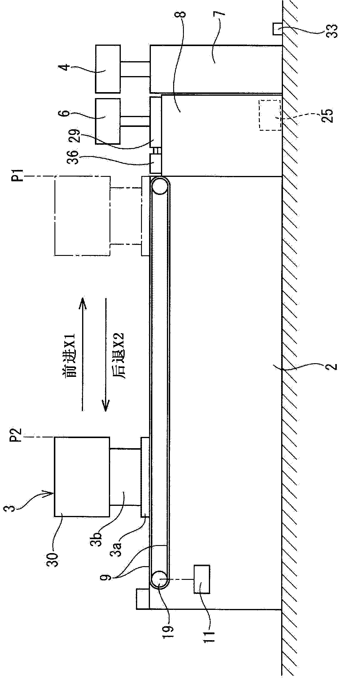
[0057] Such as figure 1 As shown, the overall structure of the bending device is provided with a conveyance path 2a along the longitudinal direction on the upper surface of the substantially rectangular shape of the base 2 fixed on the ground. The mobile trolley 3 mounted on the conveyance path 2a is advanced in the direction of the arrow X1 and stopped at the front end stop position P1, and the front end upper surface of the base 2 at a certain distance S1 from the front end stop position P1 is set to rotate. Free bending table 7, on the upper surface of the bending table 7, the bending roll mold 4 and the fastening mold 5 are arranged oppositely, and the pressure mold is arranged on the side between the bending table 7 and the front end stop position P1 6.

[0058] The mobile trolley 3 retreats from the front end stop position P1 in the direction of the arrow X2 an...


PUM


Abstract

The invention provides a pipe bending device, which is simplified and miniaturized, and a pipe bending method. A pipe chuck assembly is mounted on a movable cart which carries out reciprocation in a rectilinear direction on a base table. The pipe chuck assembly includes a chunk supporter which rotates under the driving of a chunk rotating unit on the movable cart; right and left chuck holders mounted on the chunk supporter; and a pair of chunk moulds which moves close to or away from each other by drive units fixed on the chunk supporter, and are provided with grooves fitting a semi-circumference part of the pipe on opposite faces of the chunk moulds. The bending device has a bending roller mould and a fastening mould which are positioned in front of a front stop position of the movable cart. When the pipe is inserted from above and clamped by the pair of chunk moulds on the movable cart, the pipe is rotated by the chunk rotating unit, the moving cart is moved to the front stop position, and the pipe is clamped by the bending roller mould and the fastening mould so as to be subjected to bending processing in three dimensional directions, wherein during the bending processing, the movable cart returns to a preset position.

Description

technical field [0001] The present invention relates to a tube bending device and a tube bending method. Specifically, it is suitable for three-dimensionally bending a tube in which a high-voltage cable for underfloor wiring is passed through a hollow portion in an electric vehicle or a hybrid vehicle. Tube bending device and tube bending method. Background technique [0002] In an electric vehicle or a hybrid vehicle, the wiring harness that is wired between the battery and the inverter, and between the inverter and the motor, etc. contains high-voltage cables that are sources of noise, so they are routed to the underfloor under the floor , in the underfloor wiring area, high-voltage cables may be passed through metal pipes for wiring as protection of wire harnesses and shielding measures for high-voltage cables. One end of the tube passing through the high-voltage cable is bent upward to be connected to the battery mounted on the floor, and the other end is also bent upwa...

Claims


Application Information

Patent Timeline
Patent Type & Authority Applications(China)
IPC IPC(8): B21D7/025
Inventor 大平雄贵志贺弘章桑原正纪前田贵政
Owner SUMITOMO WIRING SYST LTD
Why Eureka
Try Eureka