Load port

Inactive Publication Date: 2010-06-03
SINFONIA TECHNOLOGY CO LTD
View PDF12 Cites 16 Cited by
  • Summary
  • Abstract
  • Description
  • Claims
  • Application Information

AI Technical Summary

Benefits of technology

[0015]With the load port according to the present invention, even during a purge operation, wafers can be transferred between the inside of the FOUP and the inside of the semiconductor fabrication apparatus. Further, a FOUP can be moved suitably betw

Problems solved by technology

Therefore, the original function of the load port, that is, the function of feeding a wafer between the inside of the FOUP and the inside of the semiconductor fabrication apparatus, cannot be exhibited, resulting in a problem that the operation efficiency drops.
Besides, th

Method used


Image

  • Load port
  • Load port
  • Load port

Examples


Embodiment Construction

[0024]In the following, a load port according to a preferred embodiment of the present invention is described with reference to the drawings.

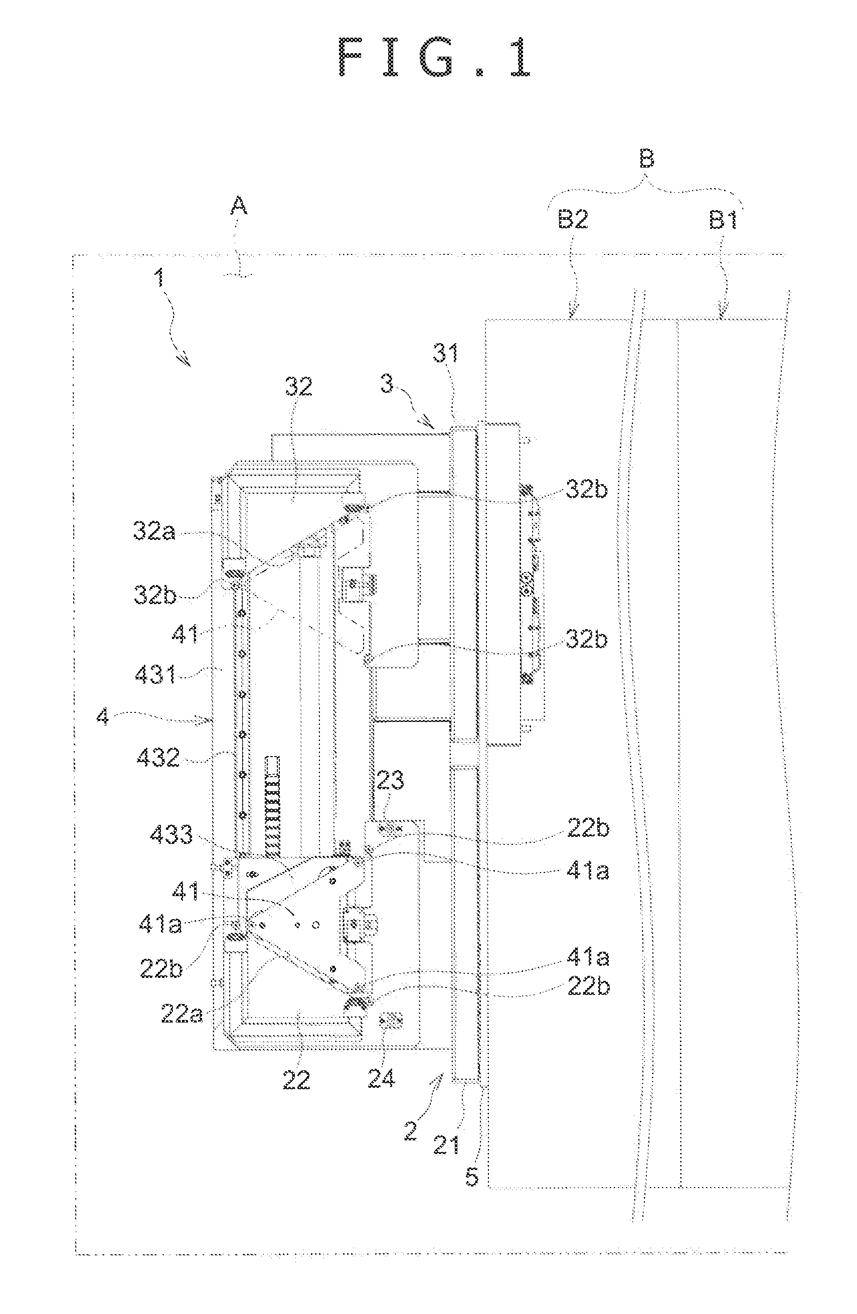
[0025]Referring first to FIG. 1, the load port 1 according to the present embodiment is used in a fabrication process of semiconductors and is disposed adjacent a semiconductor fabrication apparatus B in a common clean room A. A door of the load port 1 on a FOUP 9 side is opened and closed in a closely contacting relationship, and the load port 1 transfers a wafer (not shown) accommodated in the FOUP 9 to and from the semiconductor fabrication apparatus B. It is to be noted that FIG. 1 is a plan view of the load port 1 and peripheral elements as viewed from above and schematically illustrating a relative positional relationship between the load port 1 and the semiconductor fabrication apparatus B in the clean room A.

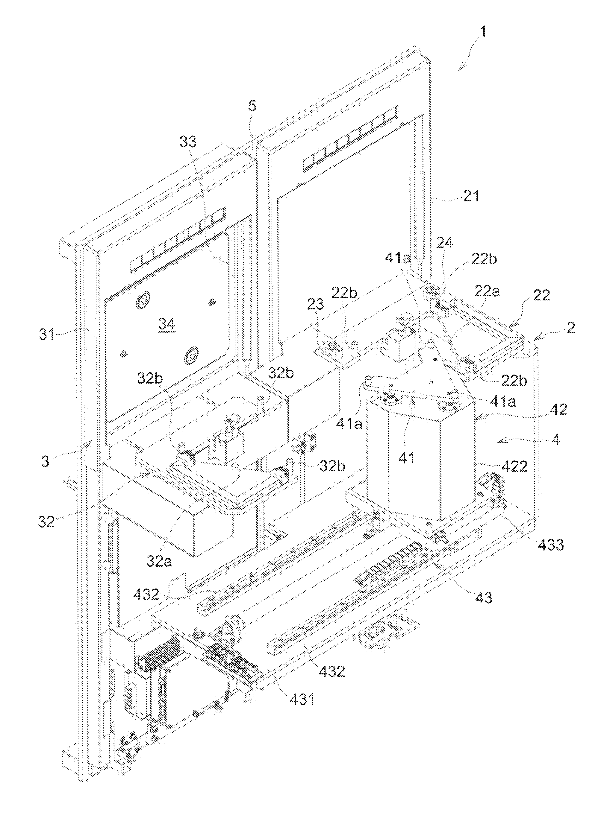
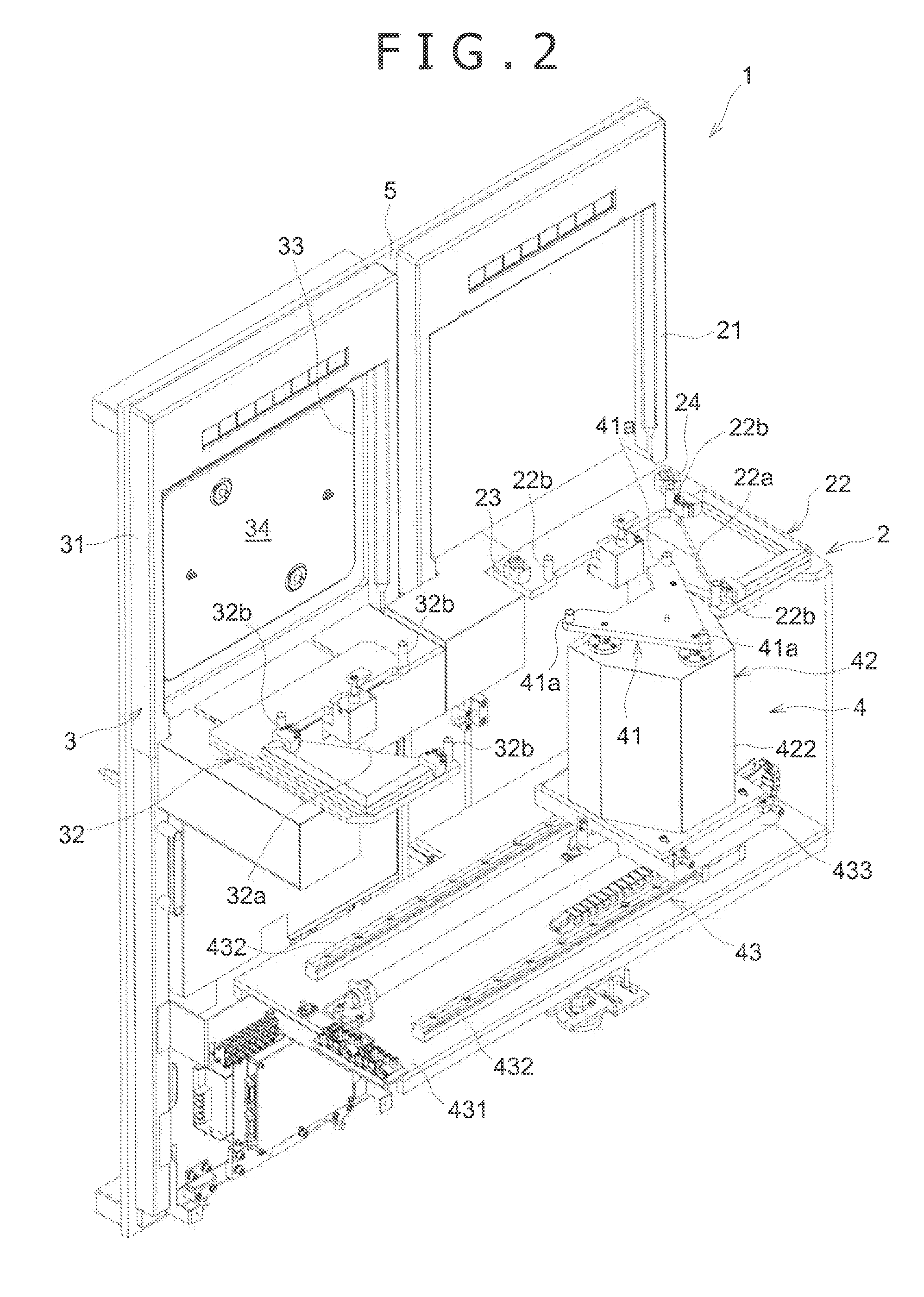
[0026]Referring to FIGS. 1 to 5 among which FIGS. 2 and 3 are schematic views of the entire load port 1 as viewed in different dir...


PUM


Abstract

A load port is disclosed which allows a wafer to be transferred between the inside of a FOUP and the inside of a semiconductor fabrication apparatus even during a purge operation. The load port is provided adjacent the semiconductor fabrication apparatus in a clean room and includes a purge stage having a purge port through which a gas atmosphere in the FOUP is replaced into nitrogen gas or dry air, an opener stage provided in a juxtaposed relationship with the purge stage and having an opening communicating with the inside of the semiconductor fabrication apparatus and a door section capable of opening and closing the opening, and a moving mechanism for moving the FOUP between the purge stage and the opener stage.

Description

BACKGROUND OF THE INVENTION[0001]1. Field of the Invention[0002]This invention relates to a load port provided adjacent a semiconductor fabrication apparatus in a clean room.[0003]2. Description of the Related Art[0004]In a fabrication process of semiconductors, processing of a wafer in a clean room is carried out in order to achieve a high yield and high quality. However, in this day of advanced high integration of devices, enhanced refinement of circuits and enhanced increase in size of wafers, it is difficult in terms of the cost and the technique to manage fine dust in an entire clean room. Therefore, in recent years, as a method to be used in place of the improvement in cleanness in the entire clean room, a countermeasure of introducing a “mini environment system” wherein the cleanness is improved only in a local space around a wafer to carry out transportation of and other processes for the wafer is adopted. In the mini environment system, a containment called FOUP (Front Open...

Claims


Application Information

Patent Timeline
IPC IPC(8): H01L21/677
CPCH01L21/67772
Inventor NATSUME, MITSUOKAWAHISA, SHINMIZOKAWA, TAKUMI
Owner SINFONIA TECHNOLOGY CO LTD
Why Eureka
Try Eureka