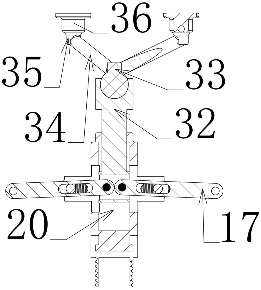
Supporting devices for civil engineering
A support device and civil engineering technology, which is applied in the field preparation of formwork/formwork/work frame, building components, construction, etc., can solve the problem that the support force cannot be adjusted, and achieve the effect of avoiding accuracy
- Summary
- Abstract
- Description
- Claims
- Application Information
AI Technical Summary
Problems solved by technology
Method used
Image
Examples
Embodiment 1
[0031] Embodiment 1, its technical solution is characterized in that it includes a load-bearing base 1, a threaded extension rod 2 rotatably connected to the load-bearing base 1, an additional force conversion device 3 that is rotatably connected to the upper end of the threaded extension rod 2, and an additional The support claw 4 that is slidingly connected to the upper end of the force conversion device 3 also includes an additional force adjustment device 5 sleeved on the outside of the threaded extension rod 2;
[0032] The additional force adjustment device 5 includes a counterweight cylinder 6 that is vertically slidably connected to the bearing base 1 on one side, and screwed on the other side of the bearing base 1 and sleeved on the threaded extension rod 2 on the other side. Sliding grooves 7 are provided on the front and rear sides of the cylinder 6, and a support plate 8 is slidably connected to the underside of the inner surface of the counterweight cylinder 6. 6 ...
Embodiment 2
[0034] Embodiment 2. On the basis of Embodiment 1, the additional force conversion device 3 includes a support sleeve 20 coaxially fixed on the upper end of the threaded extension rod 2. A support rod 15 is slidably connected to the support sleeve 20. On the support rod 15, Symmetrical horizontal rotation shafts 16 are provided, and one end of an action rod 17 is rotationally connected to each rotation shaft. 18 is rotated and slidably connected with a longitudinally arranged torque adjustment rod 19, which is horizontally slidably connected to the support sleeve 20, and the rotational center position of the torque adjustment rod 19 is controlled by a torque control device 21, and the outer end of the action rod 17 is connected to Rally bar 9.
[0035] When this embodiment is in use, the upper end of the support rod 15 is fixedly connected to the support claw 4, and when the action rod 17 rotates along the torque adjustment rod 19 in the transverse channel 18, it will push the...
Embodiment 3
[0036] Embodiment 3, on the basis of Embodiment 2, the torque control device 21 includes a worm 22 that extends laterally and is rotatably connected to the left side surface of the support sleeve 20 , cooperates with the worm 22 and is longitudinally rotatably connected to the front side of the support sleeve 20 And be positioned at the worm wheel 23 below the worm 22, the front and rear sides of the worm wheel 23 have threaded rods 24 protruding outward, the threaded rods 24 protruding in the front and rear direction are opposite in direction, the right side of the support sleeve 20 is protruding to the right and fixedly connected with a longitudinal Slide bar 25, on the threaded bar 24 that protrudes from the front and rear sides of the left side, one end of the torque adjustment rod 19 is threadedly connected, and the other end of the torque adjustment rod 19 is slidably connected on the slide bar 25, and when the worm screw 22 is rotated, it is positioned at the support slee...
PUM
 Abstract
Description
Claims
Application Information
 - R&D
- Intellectual Property
- Life Sciences
- Materials
- Tech Scout
- Unparalleled Data Quality
- Higher Quality Content
- 60% Fewer Hallucinations
Browse by: Latest US Patents, China's latest patents, Technical Efficacy Thesaurus, Application Domain, Technology Topic, Popular Technical Reports.
© 2025 PatSnap. All rights reserved.Legal|Privacy policy|Modern Slavery Act Transparency Statement|Sitemap|About US| Contact US: help@patsnap.com


